


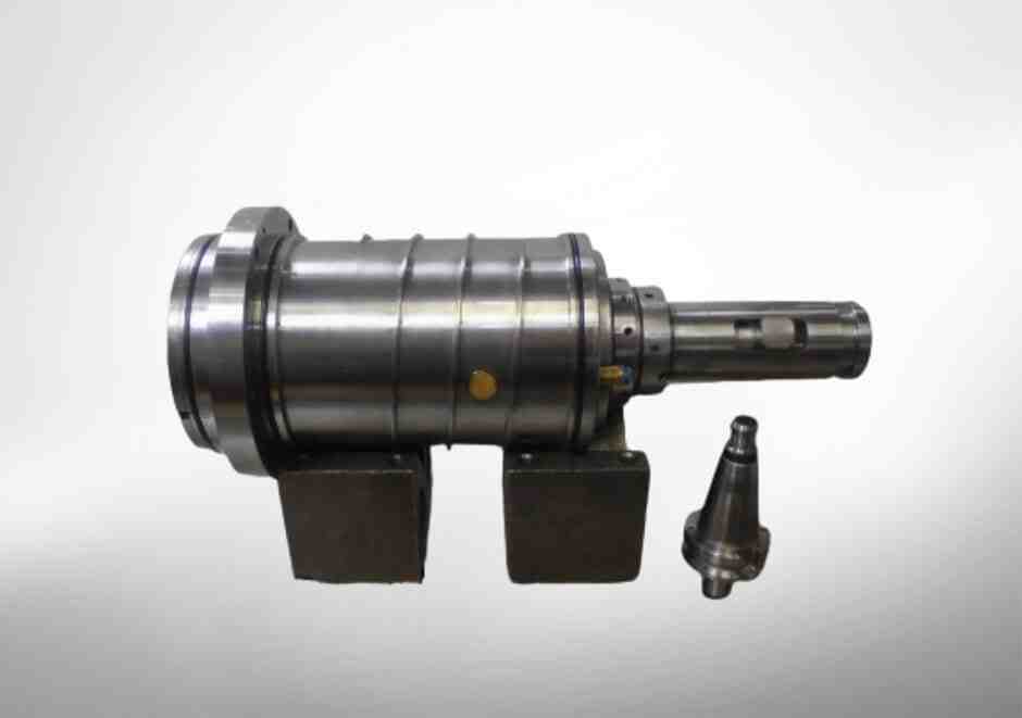
Spindle Machine Tools: A Complete Guide to Precision and Power
THE HEART OF CNC MACHINING: WHAT A SPINDLE MACHINE TOOL ACTUALLY DOES
A spindle machine tool is the rotating core of any CNC machining center — the component that holds, drives, and positions a cutting tool against a workpiece with precise speed, torque, and accuracy.
QUICK ANSWER FOR THOSE IN A HURRY:
| QUESTION | ANSWER |
|---|---|
| WHAT IS A SPINDLE MACHINE TOOL? | A precision assembly that rotates a cutting tool at controlled speeds to remove material from a workpiece |
| WHAT ARE ITS MAIN COMPONENTS? | Shaft, housing, bearings, drawbar, seals, and drive system |
| WHAT SPEEDS DO SPINDLES REACH? | Belt-driven: 12,000–15,000 RPM; integral motor: 20,000–60,000 RPM |
| WHAT CAUSES MOST SPINDLE FAILURES? | External contamination is the leading cause of premature failure |
| WHY DOES SPINDLE PERFORMANCE MATTER? | It directly determines part quality, dimensional accuracy, and machine uptime |
Every cut your CNC machine makes depends on spindle performance. The quality of machined parts — and your shop’s overall equipment efficiency — rises or falls with how well that spindle operates under demanding conditions.
Typical challenges include vibration, heat buildup, humidity, contamination, and constantly varying speed and load demands. None of these are trivial. Left unmanaged, they shorten spindle life significantly and compromise part tolerances.
This guide covers everything you need to know: core components, drive systems, bearing technologies, spindle interfaces, and how to prevent the failures that cause the most downtime in industrial manufacturing.

Simple spindle machine tool word guide:
Understanding the Spindle Machine Tool: Function and Role in CNC Machining
In industrial manufacturing, the term “spindle” refers to the entire rotating assembly that forms the core of a machine tool. When we look at modern CNC machining, the spindle machine tool acts as the primary power delivery system.
But what is its exact function? Put simply, the spindle holds the tool (in milling, routing, or drilling applications) or the workpiece (in turning applications) and rotates it to facilitate material removal. To understand how this works in practice, you can read our detailed breakdown on What is Spindle in CNC Machine.
The spindle must perform this rotation while resisting immense radial and axial cutting forces. If the spindle deflects by even a few microns under load, the dimensional accuracy of your finished part is compromised. Therefore, the spindle is not just a motor; it is a highly engineered system designed to balance speed, torque, and structural rigidity.
Anatomy of a Spindle Machine Tool
A high-performance Machine Tool Spindle is an integration of several key subsystems:
- The Shaft: The central rotating element that transmits torque from the drive system to the cutting tool.
- The Bearings: Highly precise components that support the shaft, allowing it to rotate at high speeds with minimal friction and runout.
- The Drawbar Mechanism: Located inside the hollow shaft, this spring-loaded system pulls and locks the tool holder securely into the spindle taper.
- The Housing: The outer protective shell that mounts to the CNC machine’s casting, containing the lubrication channels, cooling jackets, and electrical connections.
- The Sealing System: Front and rear seals that protect the internal precision bearings from harsh machining environments.
Primary Functions in Industrial Manufacturing
Modern industrial machining centers require spindles to execute several critical tasks simultaneously:
- Precise Speed Control: Whether running at 50 RPM for heavy-duty steel milling or 40,000 RPM for high-speed aluminum finishing, the spindle must maintain consistent speed under load.
- Rigid Tool Holding: The spindle must clamp the tool holder with thousands of pounds of force to eliminate tool chatter and deflection.
- Vibration Damping: It must absorb and dissipate the harmonic frequencies generated during metal cutting to protect both the machine and the surface finish of the workpiece.
Core Components of an Industrial Spindle
To appreciate the engineering that goes into a spindle machine tool, we have to look past the metal exterior. The internal components must work together in perfect harmony. Any misalignment or component wear will quickly show up as surface finish defects on your parts.
Every detail, from the metallurgical composition of the shaft to the geometric tolerances of the housing, plays a massive role. You can explore these design nuances further in our guide on Machine Tool Spindle Design.
The Spindle Shaft and Housing
The spindle shaft is manufactured from high-grade, heat-treated alloy steel. It is precision-ground to sub-micron tolerances to minimize dynamic runout. The shaft is hollow, which allows the drawbar to pass through and enables “coolant-through-spindle” systems to deliver high-pressure coolant directly to the cutting edge of the tool.
The housing, typically made of high-strength cast iron or specialized steel alloys, serves multiple critical functions. It provides a rigid mounting base for the bearings and incorporates internal cooling jackets. By circulating temperature-controlled liquid through these jackets, the housing manages thermal expansion, ensuring that heat generated by the motor and bearings does not warp the spindle assembly or alter the machine’s Z-axis position. To learn more about how these parts interact, check out Getting to Know Your Machine Tool Spindle.
Drawbar and Tool Retention Systems
The drawbar is the unsung hero of the spindle machine tool. It is a mechanical linkage inside the shaft that holds the tool holder in place. A stack of Belleville washer springs (or a specialized spring pack) applies massive mechanical force to pull the drawbar upward, clamping the tool holder into the spindle’s tapered nose.
To release the tool during an automatic tool change, a pneumatic or hydraulic actuator pushes down on the drawbar, compressing the spring stack and releasing the gripper mechanism (or collet). This clamping force must be incredibly high—often ranging from 1,000 to over 10,000 lbs depending on the taper size—to prevent the tool from pulling out or micro-slipping during heavy cuts.
Sealing Systems: Contact vs. Non-Contact Seals
Because external contamination is the leading cause of premature spindle failure, the sealing system is your spindle’s first line of defense.
- Contact Seals: These physical barrier seals provide excellent protection against liquid coolant and fine dust. However, because they physically ride on the rotating shaft, they generate friction and heat, which limits the spindle’s maximum operating speed.
- Non-Contact Labyrinth Seals: Used in high-speed spindles, these seals feature a complex, winding pathway (a labyrinth) that makes it physically difficult for liquid or dust to enter. To maximize protection, these systems are often paired with an air purge system, which introduces positive internal air pressure to blow away any encroaching contaminants.
Spindle Drive Systems and Bearing Technologies
How the spindle receives its rotational power and how that power is supported by bearings determines what materials the machine can cut efficiently.
| Drive Type | Speed Range | Torque Capacity | Best Used For |
|---|---|---|---|
| Gear-Driven | Low (Up to 6,000 RPM) | Extremely High | Heavy-duty roughing, large steel/titanium parts |
| Belt-Driven | Moderate (Up to 15,000 RPM) | Moderate to High | General-purpose milling, job shop environments |
| Integral Motor | High (Up to 60,000+ RPM) | Low to Moderate | High-speed machining, aluminum, mold making |
Belt-Driven, Gear-Driven, and Integral Motor Spindles
The three primary drive configurations each offer distinct advantages:
- Gear-Driven Spindles: These utilize a gearbox to multiply motor torque. While they are limited in speed, they are the undisputed kings of heavy-duty, low-speed machining where maximum metal removal rates are required.
- Belt-Driven Spindles: A highly reliable and cost-effective design where a belt connects the motor to the spindle shaft. These are standard on general-purpose machines like those from Kent Industrial USA: Precision Machine Tools for Sale and are perfect for everyday job shop work.
- Integral Motor (Motorized) Spindles: In this high-performance configuration, the motor’s rotor is shrunk-fit directly onto the spindle shaft, and the stator is housed inside the spindle body. This eliminates belts and gears, allowing for incredibly smooth rotation, minimal vibration, and extreme speeds up to 60,000 RPM. Advanced multi-axis machines, such as the U5-630 | SPINNER Machine Tools, rely heavily on these integrated designs to achieve high-speed precision.
Bearing Systems: Steel vs. Hybrid Ceramic
Spindle bearings must handle extreme rotational speeds while keeping shaft deflection to a minimum.
Traditionally, high-precision steel angular contact ball bearings were the industry standard. However, modern high-performance spindles increasingly utilize hybrid ceramic bearings. These bearings pair high-grade steel rings with silicon nitride (ceramic) balls.
Ceramic balls are 60% lighter than steel, significantly reducing centrifugal forces inside the bearing at high speeds. They also have a much lower thermal expansion coefficient, meaning they generate less friction and heat. This allows hybrid ceramic bearings to run at 15–20% higher maximum speeds than all-steel bearings while doubling the life of the lubricating grease.
Tool Retention and Spindle Interfaces
The mechanical connection between the cutting tool and the spindle machine tool is known as the spindle interface. This connection is critical because it dictates how much torque can be transmitted to the tool and how much lateral bending force the system can withstand.
Selecting the Right Spindle Machine Tool Interface
Over the years, several taper designs have emerged to meet different machining demands:
- Steep Taper (CAT, BT, NMTB): The traditional 7/24 taper design. While highly reliable and cost-effective, steep tapers lack face contact. At high rotational speeds, the spindle nose expands slightly, causing the tool holder to be drawn deeper into the taper, which changes the Z-axis tool position.
- BIG-PLUS®: This system addresses the limitations of the steep taper by providing dual contact—clamping simultaneously on both the taper and the spindle face. This dramatically increases bending stiffness and axial accuracy.
- HSK Interface: A hollow, short taper design developed for high-speed machining. When the HSK drawbar clamps, its internal segment gripper expands outward, pulling the tool holder tight against the spindle face. As rotational speed increases, centrifugal force actually increases the clamping pressure, making HSK exceptionally stable at high RPMs.
- Coromant Capto®: A unique, tapered polygon coupling. Because it features a polygon shape rather than drive keys, it provides unmatched torque resistance and bending stiffness. In static tests, a Coromant Capto C6 coupling provides 2.29 times better torque resistance than an HSK-A 63 interface, making it the premier choice for multi-tasking machines that perform both turning and milling.
Spindle Maintenance, Monitoring, and Rebuilding
A spindle is a wear item. No matter how well engineered it is, the combination of speed, load, and environment will eventually take its toll. However, you can significantly extend your spindle’s operating life by following the strategies outlined in Extending the Service Life of Your Machine Tool Spindle.
Common Causes of Spindle Failure
Understanding why spindles fail is the first step toward preventing downtime:
- Contamination: The leading cause of premature failure. Liquid coolant, fine metal chips, and abrasive dust bypass worn seals and degrade the bearing grease, leading to rapid bearing wear.
- Lubrication Failure: Too little lubricant causes friction and catastrophic heat buildup; too much lubricant causes “churning,” which also generates excessive heat.
- Crash Damage: Even a minor collision between the tool and the workpiece can dent the bearing raceways (brinelling), causing immediate vibration and rapid spindle decline.
- Improper Preload: If the bearing preload is set incorrectly during assembly, the bearings will either lack stiffness (too loose) or overheat and fail prematurely (too tight).
The Rebuilding and Repair Process
When a spindle begins to show signs of wear—such as increased vibration, excessive heat, or poor surface finishes on machined parts—it is time for a professional rebuild.
At MZI Precision, our rebuild process is incredibly thorough. We completely disassemble the unit in our controlled facility, inspect all components under magnification, and perform precision grinding to restore worn shafts and housing bores to original OEM specifications.
Crucially, we perform dynamic balancing on every rebuilt spindle. Balancing the spindle shaft to G0.4 or better at its maximum operating speed is essential to eliminate high-frequency harmonics that destroy bearings and degrade part quality.
If you are experiencing spindle issues in Southern California, we provide specialized regional support. You can learn more about our local capabilities through our dedicated services for Machine Tool Spindle Repair California and Machine Tool Spindle Repair California 341304.
Frequently Asked Questions about Spindle Machine Tools
What is the difference between a cartridge spindle and a block spindle?
A cartridge spindle has a cylindrical body designed to slide into a precision bore on the machine head. This makes cartridge spindles incredibly fast and easy to replace or swap out for servicing without requiring extensive re-tramming of the machine.
A block spindle features a rectangular, boxed housing that bolts directly onto a flat mounting surface. While block spindles are much more rigid and can handle heavier cutting loads, replacing them is a more labor-intensive process that requires meticulous realignment and tramming.
Why do hybrid ceramic bearings outperform steel bearings in high-speed spindles?
Hybrid ceramic bearings utilize silicon nitride balls instead of steel balls. Ceramic is significantly harder and lighter than steel. Because they are lighter, they generate far less centrifugal force at high RPMs, which keeps operating temperatures low. Additionally, ceramic does not micro-weld to steel under extreme loads, which virtually eliminates the risk of adhesive wear (scuffing) and dramatically extends grease life.
How does contamination cause spindle failure?
Machining environments are incredibly hostile. High-pressure coolant, fine metal particles, and abrasive dust are constantly flying around the spindle nose. If the front seals or air-purge systems fail, these contaminants migrate into the precision bearings. The particles act as an abrasive grit, scratching the polished raceways, while the coolant dilutes and washes away the lubricating grease. This leads to immediate metal-on-metal friction, rapid heat buildup, and catastrophic bearing seizure.
Conclusion
Your CNC machines are only as productive as the spindles driving them. Choosing the right drive system, bearing configuration, and tool interface for your specific manufacturing needs is essential to optimizing your shop’s efficiency and part quality.
When your spindle eventually requires attention, cutting corners on the repair is a recipe for repeat failures. At MZI Precision, we specialize in high-precision, OEM-quality spindle rebuilding and repair. From our advanced testing and dynamic balancing to our deep expertise in complex motorized and belt-driven designs, we ensure your equipment is restored to peak performance.
If you are looking to restore the precision and power of your machining operations, visit our Machine Tool Spindle Rebuild page or contact us directly via our Machine Tool Spindle Repair service portal. Let us help you keep your spindle machine tools running smoothly and reliably.