


Why Understanding Maximum Spindle Speed in CNC Machine Operations is Critical
Maximum spindle speed in cnc machine operations typically ranges from 6,000 to 30,000 RPM for industrial manufacturing, though high-speed spindles can exceed 100,000 RPM. Here’s what determines your limits:
Key Factors Setting Maximum RPM:
– Bearing diameter and type – smaller bearings = higher speed, less power
– Chuck and fixture limits – safety ratings prevent catastrophic failure
– Tool balance requirements – G2.5 standard above 10,000 RPM
– Machine design specifications – OEM ratings and cooling capacity
– Workpiece balance condition – out-of-round parts need reduced speeds
When you’re pushing your CNC to its limits, spindle speed becomes your biggest bottleneck. Run too slow and you’re leaving money on the table. Run too fast and you risk bearing failure, poor surface finish, or worse – a chuck explosion that could seriously hurt someone.
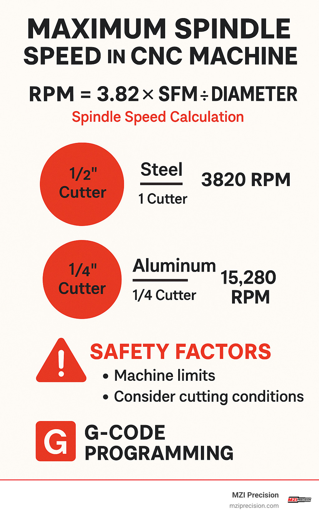
Most shops only use about 50% of their spindle’s actual capacity because they don’t understand the relationship between cutting speed, tool diameter, and safe operating limits. The formula is simple: RPM = 3.82 × SFM ÷ diameter, but knowing when to push those limits requires understanding your machine’s true capabilities.
The stakes are high. A single spindle rebuild can cost $15,000-$30,000 and take weeks of downtime. But operated correctly at optimal speeds, that same spindle can cut cycle times by 48% and dramatically improve your bottom line.
This guide will show you exactly how to determine your maximum safe spindle speed, program it correctly, and operate at peak efficiency without destroying expensive components.
Maximum spindle speed in cnc machine definitions:
– cnc multi spindle machine
– grinding spindle
– spindle for cnc router machine
Spindle Speed Fundamentals
Think of spindle speed like driving a car – you need to understand the relationship between your speedometer and how fast your wheels are actually turning. In CNC machining, we deal with two critical measurements that work together: RPM (revolutions per minute) and SFM (surface feet per minute).
Here’s where it gets interesting. Cutting speed is the linear velocity at which your cutting edge moves past the workpiece material. This movement creates the friction and heat that actually removes material. It’s like rubbing your hands together – rub faster, and you generate more heat. The same principle drives every cut your machine makes.
The magic formula connecting these concepts is simple: RPM = 3.82 × SFM ÷ diameter. This relationship reveals something crucial about maximum spindle speed in cnc machine operations. As your tool diameter shrinks, you need higher RPM to maintain the same cutting speed. Use a larger tool? You’ll need lower RPM to avoid destroying it with excessive cutting speeds.
Bearing diameter plays a starring role in determining your spindle’s maximum capabilities. Smaller bearings can spin incredibly fast but handle less power. Larger bearings run slower but support heavier cutting loads. It’s a fundamental physics trade-off – high-speed spindles often sacrifice torque for speed because you simply can’t have both.
The vibration-RPM² law is something every machinist should understand. Vibration forces increase with the square of rotational speed. Double your RPM, and you create four times the vibration stress on bearings and machine components. This exponential relationship explains why tool balancing becomes absolutely critical above 10,000 RPM.
The torque curve of your spindle motor tells an important story too. Most AC motors provide constant torque up to their base speed, then shift to constant power as speed increases. This means maximum torque happens at lower speeds, while maximum power occurs at higher speeds.
For deeper insights, scientific research on high-speed machining reveals even more complex relationships that emerge at extreme speeds.
Why RPM and SFM Matter
Heat generation during cutting is directly tied to cutting speed. Run too slow, and you’re not efficiently removing material or getting optimal tool life. Push too fast, and excessive heat destroys cutting edges while creating poor surface finishes.
Tool life follows a predictable curve based on cutting speed. There’s a sweet spot where you maximize both productivity and tool longevity. Push beyond this point, and tool costs skyrocket. Stay too conservative, and you’re wasting valuable time and machine capacity.
Surface finish quality depends heavily on spindle speed consistency and vibration control. Higher speeds often produce better finishes when properly controlled, but only if your entire system can maintain stability throughout the cut.
The Role of Bearings and Motor Power
Bearing size fundamentally limits your maximum spindle speed. Small bearings in high-speed applications typically use ceramic balls and specialized lubrication systems. These can exceed 100,000 RPM but come with limited power capacity.
Preload settings affect both speed capability and bearing life in ways that might surprise you. Too little preload allows excessive play and vibration. Too much preload increases friction and heat, which limits maximum speed. Getting preload right is critical for achieving your spindle’s rated performance.
Lubrication method determines speed limits more than most operators realize. Grease-packed bearings typically max out around 20,000-24,000 RPM. Oil mist or air-oil systems can support much higher speeds but require more complex maintenance schedules.
AC motor characteristics provide constant torque up to base speed, then constant power as speed increases. Understanding this power curve helps you optimize cutting parameters and get the most from your machine’s capabilities.
Determining the Maximum Spindle Speed in CNC Machine
Finding the maximum spindle speed in cnc machine operations isn’t as simple as reading a number off the nameplate. Your actual limit depends on the weakest link in your entire system – and trust me, there are more weak links than you might think.
Your OEM rating gives you the theoretical ceiling, but real-world operations rarely reach those numbers safely. That shiny 20,000 RPM rating on your spindle means nothing if your 8-inch hydraulic chuck taps out at 6,000 RPM. Physics doesn’t care what your marketing brochure says.
Chuck limits often become your real bottleneck before spindle limits ever come into play. Centrifugal force increases with the square of RPM, which means doubling your speed creates four times the stress on chuck components. This is why chuck manufacturers are conservative with their speed ratings – they’ve seen what happens when operators push too hard.
Tool holder balance becomes absolutely critical above 10,000 RPM. The ISO G2.5 standard exists for good reason – unbalanced tools create vibration forces that grow exponentially with speed. We’ve seen operators destroy $30,000 spindles in minutes because they ignored balance requirements. Don’t be that person.
Key Factors Setting the Maximum Spindle Speed in CNC Machine
Machine design sets your absolute ceiling, and there’s no negotiating with physics. Your spindle bearing specifications, housing rigidity, and thermal management systems work together to determine safe operating limits. These aren’t suggestions – they’re hard boundaries that will bite you if ignored.
Bearing limitations vary dramatically based on type, size, and lubrication method. Rolling element bearings have different speed capabilities than air bearings. Ceramic bearings can outperform steel at high speeds, but they cost significantly more and need specialized maintenance knowledge.
Cooling system capacity determines whether you can sustain high-speed operation or just run brief bursts. Air cooling works fine for intermittent high-speed work, but continuous operation above 20,000 RPM demands liquid cooling. Thermal growth and bearing temperature directly impact how fast you can safely spin.
Workpiece balance condition dramatically affects your safe operating speed. A perfectly round, balanced part might handle full spindle speed without breaking a sweat. But that out-of-round casting sitting in your fixture? You might need to cut your speed in half to prevent dangerous vibration that could damage your machine.
Fixture strength must withstand the centrifugal forces at maximum speed. We’ve witnessed fixtures fail catastrophically when operators ignored speed limitations. The forces involved can literally tear apart inadequately designed workholding systems.
Calculating Recommended RPM for Materials & Tools
The basic formula RPM = 3.82 × SFM ÷ diameter gives you the mathematical starting point, but material-specific SFM values determine your actual operating speeds. Aluminum typically runs at 500-1000 SFM, while mild steel needs 150-300 SFM. Stainless steel requires more conservative 100-200 SFM speeds, and titanium demands even gentler 50-150 SFM approaches. Cast iron falls in the middle at 200-400 SFM, while plastics can handle aggressive 300-800 SFM speeds.
Cutter diameter has an inverse relationship with RPM that catches many operators off guard. A 1-inch end mill in aluminum at 500 SFM needs 1,910 RPM. But drop down to a 0.125-inch end mill, and you need 15,280 RPM for the same cutting speed. This relationship explains why small tools drive the demand for high-speed spindles.
Tool material and coating significantly affect recommended speeds. Carbide tools typically run 3-5 times faster than HSS tools while maintaining reasonable tool life. Coated tools push these limits even further, and modern ceramic or CBN tools operate in speed ranges that would destroy conventional tooling.
Risks of Exceeding the Maximum Spindle Speed in CNC Machine
Bearing failure tops the list of overspeed consequences. Bearings are precisely engineered for specific speed ranges, and exceeding these limits causes rapid wear and catastrophic failure. A typical industrial spindle rebuild runs $15,000-$30,000 and takes weeks of downtime – not exactly a budget-friendly mistake.
Chuck explosion represents the most dangerous overspeed scenario imaginable. Centrifugal forces can cause chuck jaws or the entire chuck assembly to fail catastrophically, sending metal fragments at lethal velocities through your shop. This isn’t theoretical – it happens, and it’s why chuck speed ratings exist and must never be exceeded.
Poor surface finish often results from excessive speed causing vibration, chatter, or thermal issues. What starts as an attempt to boost productivity quickly becomes a quality nightmare requiring additional finishing operations. Sometimes slower really is faster.
Safety hazards multiply exponentially at high speeds. Tool failures become more violent, workpiece ejection more dangerous, and machine damage more severe. Proper safety protocols and realistic speed limits protect both your operators and your expensive equipment.
Programming and Controlling Spindle Speed Safely
Programming your maximum spindle speed in cnc machine safely isn’t just about knowing the right G-codes – it’s about understanding how these commands protect your equipment and your operators. Modern CNC controls give you powerful tools to manage spindle speed, but with that power comes responsibility.
The beauty of today’s controls lies in their sophistication. G96 constant surface speed automatically adjusts RPM as your tool moves across different diameters, keeping cutting conditions consistent. Think of it like cruise control for your cutting speed – it maintains optimal performance without constant manual adjustments.
But here’s the catch: G96 without proper limits can be dangerous. When facing a part down to center, the control tries to maintain surface speed by increasing RPM. Without a speed clamp, it would theoretically spin infinitely fast as diameter approaches zero. That’s where smart programming saves the day.
G97 fixed RPM mode gives you precise control when you need it. Operations like drilling, tapping, or working with delicate fixtures require specific RPM regardless of diameter changes. Some materials and tool geometries simply work better at constant RPM rather than varying speeds.
G50 speed clamp acts as your safety net, setting an absolute maximum RPM that won’t be exceeded. This simple command can prevent catastrophic overspeed failures that cost thousands in repairs and downtime. Parameter limits in your machine provide another layer of protection, while spindle range codes help optimize power delivery across different speed ranges.
For detailed technical information about constant surface speed limiting spindle speed, proper implementation becomes critical for both safety and productivity.
Setting or Limiting Maximum RPM with G-codes
Programming G50 S1500 tells your machine “never exceed 1,500 RPM, no matter what.” It’s that simple, yet this one line of code can save you from expensive spindle rebuilds. Always program your speed limit before any operation that might cause unexpected speed increases.
Smart programmers build safety into every program. A typical safe start block might include G50 S3000 followed by G97 S1000 M03. This ensures your spindle starts at a known, safe speed before ramping up to working conditions.
G92 provides an alternative speed limiting method on some controls, though its behavior varies between manufacturers. While similar to G50, always check your specific control manual – assuming they work identically can lead to unpleasant surprises.
Fanuc parameter adjustments offer machine-level protection through parameters P3741-P3743 for maximum spindle speeds and P4020 for motor speed limits. These require careful calculation based on your spindle-to-motor reduction ratios, but they provide an extra safety layer that operators can’t accidentally override.
Constant Surface Speed vs Constant Spindle Speed
G96 advantages shine when you’re working across varying diameters. Imagine turning a part from 4 inches down to 1 inch diameter – CSS automatically increases RPM to maintain optimal cutting speed throughout the operation. This consistency can reduce cycle times by 20-40% while actually improving tool life.
The efficiency gains from proper CSS programming are substantial. Operations that previously required multiple tool changes or manual speed adjustments can now run continuously at optimal parameters. Your tools stay happy, your surface finish stays consistent, and your cycle times drop significantly.
G97 use-cases include drilling, tapping, and any operation requiring specific RPM for proper chip formation. Some materials respond better to constant RPM, especially when dealing with interrupted cuts or specialized tool geometries that need consistent rotational dynamics.
Diameter changes during operations like facing demonstrate why speed limiting is non-negotiable. Without G50, facing to center would drive RPM toward infinity as diameter approaches zero. The control hits your programmed limit instead, keeping everything safe and controlled.
Understanding when to use each mode makes the difference between good programmers and great ones. CSS maximizes efficiency for turning and contouring operations, while constant RPM ensures reliability for hole-making and threading operations.
Best Practices for Operating Near Maximum Speed
When you’re pushing your spindle to its limits, every detail matters. Maximum spindle speed in cnc machine operations demand a methodical approach that many shops learn the hard way – through expensive failures that could have been prevented.
Think of high-speed spindle operation like driving a race car. You wouldn’t floor it from a cold start, and you certainly wouldn’t ignore the warning lights on your dashboard. The same principles apply to your CNC spindle.
Warm-up routines become absolutely critical at high speeds. A cold spindle with pooled lubricants is like trying to pump thick honey through tiny passages. When you suddenly jump to maximum RPM, those bearings can overheat in minutes. Instead, gradually increase RPM over 10-20 minutes, allowing lubricants to distribute properly and temperatures to stabilize. Your bearings will thank you with years of additional service life.
Balanced toolholders are non-negotiable above 10,000 RPM. The G2.5 balance standard isn’t just a suggestion – it’s the difference between smooth operation and catastrophic bearing failure. Vibration forces increase with the square of RPM, so an unbalanced tool that seems fine at 5,000 RPM becomes a destructive force at 15,000 RPM.
Your coolant and lubrication systems must function flawlessly at maximum speeds. We’ve seen too many spindles destroyed by contaminated coolant or inadequate lubrication flow. At high speeds, there’s no margin for error – dedicated filtration systems and high-quality lubricants aren’t luxuries, they’re necessities.
Vibration monitoring provides your early warning system before problems become disasters. Modern sensors can detect bearing wear, tool imbalance, and other issues while they’re still correctable. The cost of monitoring equipment is insignificant compared to a $25,000 spindle rebuild and weeks of downtime.
Thermal stability affects everything – accuracy, surface finish, and component life. High-speed operation generates heat that causes expansion and affects tolerances. Proper thermal management includes both adequate cooling systems and patience during warm-up. Rushing this process almost always leads to problems down the road.
Power, Torque & Productivity Trade-offs
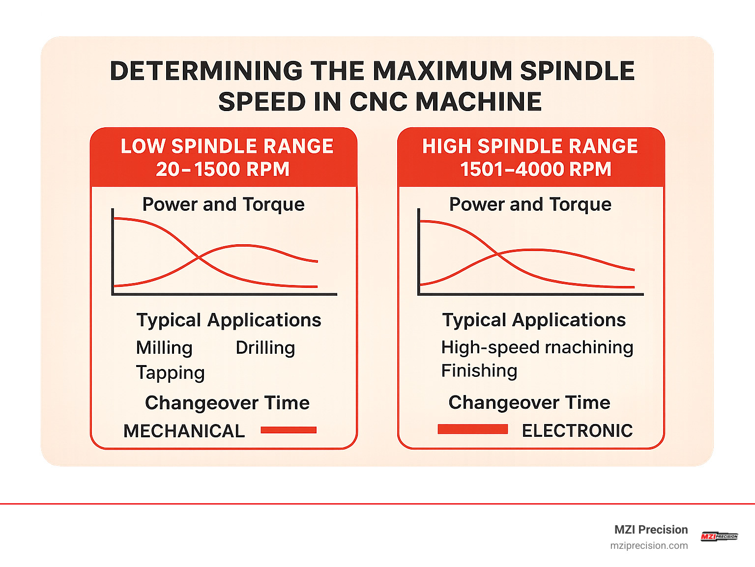
Understanding your spindle’s power characteristics is like knowing your car’s transmission. Low versus high spindle ranges offer completely different capabilities. Low ranges typically provide 0-2,000 RPM with maximum torque for heavy roughing cuts. High ranges might offer 0-6,000 RPM or more, but with reduced torque that’s perfect for finishing operations.
Power curve reading reveals the sweet spots in your spindle’s performance. Most industrial spindles provide constant torque up to base speed, then constant power as speed increases. This means your maximum power is only available at higher speeds – understanding this relationship helps you optimize cutting parameters for each operation.
Cycle time impact depends heavily on proper range selection. Roughing operations might benefit from low-range, high-torque cutting that removes material quickly. Finishing operations typically need high-range speeds for optimal surface quality. The key is matching your spindle range to the cutting requirements.
Spindle range changes aren’t instantaneous. Mechanical transmissions might require several seconds for gear changes, while electronic systems switch almost immediately. Planning your toolpaths to minimize range changes can shave significant time off complex operations.
Maintenance Steps to Extend Spindle Life at High RPM
High-speed operation is like city driving – it’s harder on your equipment than steady highway cruising. Routine inspections should include vibration measurement, temperature monitoring, and careful examination of toolholders and spindle components. What might be acceptable wear at normal speeds becomes critical at maximum RPM.
Lubrication schedules become more aggressive at high speeds. While a standard spindle might run 6,000 hours between services, high-speed operation often requires service every 3,000-4,000 hours. Quality lubricants and proper filtration can help extend these intervals, but there’s no substitute for regular maintenance.
Temperature checks during operation help identify problems before they become failures. Bearing temperatures above normal ranges indicate lubrication problems, overloading, or impending failure. Thermal imaging cameras can identify hot spots weeks before they become critical issues.
Predictive maintenance programs using vibration analysis, oil analysis, and thermal monitoring can predict failures months in advance. This allows you to schedule maintenance during planned downtime rather than dealing with emergency repairs during critical production runs. The investment in monitoring equipment typically pays for itself with the first prevented failure.
Frequently Asked Questions about Maximum Spindle Speed
What happens if I accidentally exceed the programmed limit?
Don’t panic – modern CNC controls are pretty smart about protecting your equipment. If you accidentally exceed a G50 speed limit, your control will automatically clamp the spindle at your programmed maximum. It’s like having a safety net that catches you before you fall.
But here’s where things get serious. If you somehow bypass the control’s protection and exceed the actual machine limits, you’re in dangerous territory. The consequences depend on how far over the limit you go and how long you stay there.
A brief overspeed event might not cause immediate visible damage, but it’s like running your car engine in the red zone – you’re shortening the life of expensive components. Maximum spindle speed in cnc machine operations have these limits for good reason.
Sustained overspeed operation is where things get expensive fast. We’ve seen spindle bearings destroyed in less than five minutes when operators ignored speed warnings. A $30,000 rebuild and three weeks of downtime tends to get management’s attention quickly.
How can I test and verify a safe top speed for a specific setup?
Testing maximum safe speed requires patience and a systematic approach. Think of it like test-driving a new car – you don’t immediately floor it on the highway.
Start by using Manual Data Input (MDI) mode to control speed precisely. Begin at about 25% of your theoretical maximum and work your way up in 10% increments. Listen carefully for changes in vibration, noise, or any unusual sounds that indicate distress.
The key is testing with your actual workpiece setup, not just an empty spindle. That rough casting or unbalanced part will behave very differently than a perfectly balanced test piece. We always recommend testing multiple workpieces to find your worst-case scenario.
Watch for the vibration threshold – that point where things start getting shaky. Once you find it, back off by 10% for your programmed limit. This gives you a safety margin that accounts for variations in workpieces and normal wear over time.
Always test in your high spindle range if you plan to use it. Testing in low range and assuming high range will behave the same way is like testing a bicycle and expecting the same results in a race car.
Are there materials where running at maximum spindle speed is not advisable?
Absolutely. Some materials are like that friend who needs special handling – they don’t play well with maximum speeds.
Work-hardening materials like stainless steel can actually get harder and more difficult to machine if you generate too much heat. These materials often prefer moderate speeds that keep temperatures under control. Push too hard and fast, and you’ll end up with work-hardened surfaces that dull your tools quickly.
Very hard materials like hardened steels or exotic alloys might require slower speeds to prevent tool breakage. It’s not always about going fast – sometimes it’s about surviving the cut.
But here’s the thing – workpiece condition often matters more than material type. A rough casting with heavy interrupted cuts needs reduced speeds regardless of whether it’s aluminum or steel. The vibration and shock loads from interrupted cutting can damage your spindle even if the material itself could handle high speeds.
Long, slender workpieces present their own challenges. They might start vibrating like a tuning fork at high speeds, even if your spindle could theoretically handle the load. In these cases, workpiece dynamics become your limiting factor, not spindle capability.
The bottom line? Maximum spindle speed in cnc machine operations isn’t just about what your spindle can do – it’s about what your entire setup can handle safely and effectively.
Conclusion
Finding the sweet spot for maximum spindle speed in cnc machine operations isn’t about pushing every limit – it’s about understanding where precision, productivity, and safety intersect. Think of it like driving a sports car: just because it can hit 180 mph doesn’t mean that’s always the smart choice.
The relationship between cutting speed and RPM (RPM = 3.82 × SFM ÷ diameter) gives you the math, but the real world adds complexity. Your bearings might handle 30,000 RPM, but your chuck tops out at 6,000. Your spindle could theoretically run faster, but thermal growth starts affecting your tolerances. These competing factors create your actual operating window.
Smart programming makes all the difference. G96 constant surface speed mode can slash cycle times and extend tool life, but only when paired with proper G50 speed limiting. We’ve seen shops gain 30% productivity just by programming smarter, not necessarily running faster.
The shops that succeed long-term understand that maximum spindle speed in cnc machine operations requires respect for the entire system. They invest in balanced toolholders, maintain proper warm-up routines, and monitor vibration religiously. They know that an ounce of prevention beats paying for a $25,000 spindle rebuild.
At MZI Precision, we’ve rebuilt thousands of spindles from shops that learned these lessons the hard way. The most successful operations we work with aren’t necessarily running at absolute maximum speeds – they’re running at optimal speeds that balance throughput with reliability.
Your goal should be finding that optimal zone where your spindle purrs along efficiently for years, not screams for a few months before requiring emergency service. With proper understanding of speed limits, careful programming, and systematic maintenance, you can extract maximum value from your investment while sleeping soundly at night.
For more information about maintaining your spindle at peak performance, visit our CNC spindle rebuilding services page to learn how we can help optimize your operations.