


The Heart of Precision Manufacturing
When machinists talk about the “heart” of their CNC machine, they’re not being poetic—they’re being literal. Just as your heart pumps life-giving blood throughout your body, a well-designed Machine Tool Spindle Design delivers the power, precision, and performance that transforms raw materials into finished masterpieces.
Think of your spindle as the unsung hero of manufacturing. While operators and programmers get the glory, it’s this rotating assembly quietly humming away that determines whether your aerospace components, medical implants, or precision parts meet spec or end up in the scrap bin.
Machine Tool Spindle Design is both art and science. Engineers must balance competing demands—speed versus torque, accuracy versus cost, and durability versus weight. It’s like trying to build a Formula 1 car that can also haul lumber!
The foundation of any spindle system starts with its drive mechanism. Belt-driven systems offer a cost-effective solution for operations requiring substantial torque at speeds up to 15,000 RPM. For those needing higher precision and speed, direct-drive and integral motor designs can reach an impressive 60,000 RPM—perfect for those finishing operations where surface quality is everything.
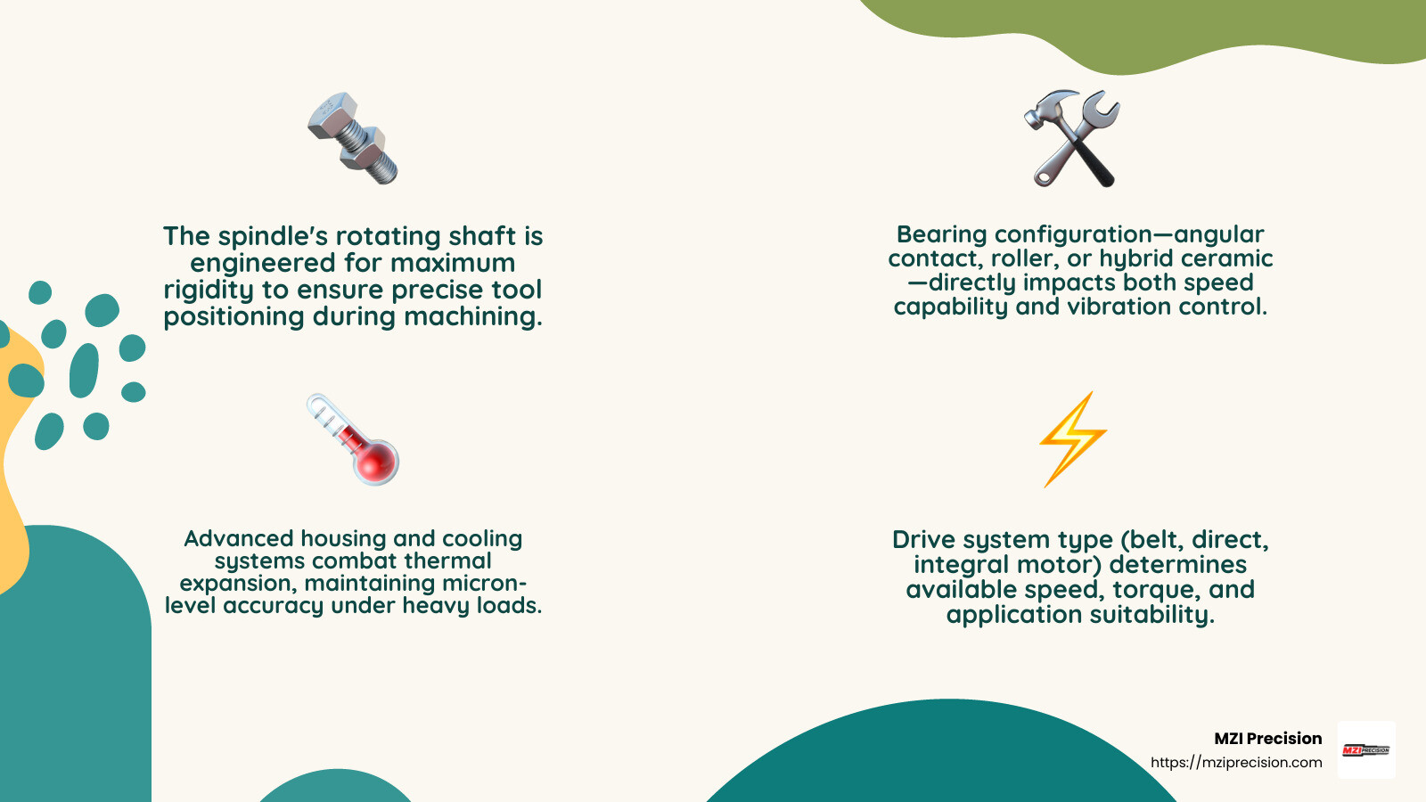
Bearing selection is equally crucial. Whether using traditional angular contact bearings, roller bearings for heavy loads, or hybrid ceramic bearings for high-speed applications, this choice directly impacts your machine’s performance envelope and longevity.
As one industry veteran once told me, “A precision spindle isn’t just designed—it’s orchestrated.” Each component—from the housing that manages thermal growth to the cooling system that maintains dimensional stability—works in harmony to deliver consistent results part after part.
For manufacturing professionals, choosing the right spindle isn’t about picking the fastest or most expensive option. It’s about understanding your specific application requirements and finding the optimal balance. When machining titanium aerospace components, you’ll need different spindle characteristics than when producing aluminum automotive parts or stainless steel medical devices.
The beauty of modern Machine Tool Spindle Design is the range of options available. From robust workhorses that power through tough materials to high-speed precision units that create mirror finishes, today’s spindle technology offers solutions for virtually every manufacturing challenge.
Remember—behind every perfectly machined part is a precisely designed and maintained spindle. It may not be the most visible component in your shop, but it might just be the most important.
Machine Tool Spindle Design: Foundations of Precision
At the heart of every precision machining center lies the spindle – a marvel of engineering that transforms raw power into precise cutting motion. Machine tool spindle design is both an art and a science, where every component must work in perfect harmony to achieve micron-level accuracy.
Think of a spindle as an orchestra conductor, directing all the cutting action with unwavering precision. The fundamental architecture includes several critical components working together:
The rotating shaft serves as the central element, holding cutting tools while transmitting rotational energy. Surrounding this is the housing, which provides not just structural support but contains essential cooling passages and lubrication channels that keep everything running smoothly. The bearing system allows the shaft to rotate with minimal friction while maintaining rigid support, while the drawbar mechanism ensures tools stay securely clamped with consistent force throughout operation. Finally, the drive system (whether belt, gear, or direct) delivers the necessary power to make it all work.
“As designers, we’re constantly balancing competing priorities – speed, power, stiffness and cost,” explains one of our senior engineers at MZI Precision. “It’s like trying to optimize a recipe where changing one ingredient affects everything else.”
When spindles rotate at high speeds – often exceeding 20,000 RPM – they face enormous challenges from centrifugal forces and thermal expansion. These physical realities must be accounted for through meticulous engineering calculations and material selection.
The Role of Machine Tool Spindle Design in Accuracy
In precision manufacturing, we measure success in microns – thousandths of a millimeter. Two metrics reign supreme when evaluating machine tool spindle design:
Runout measures how much the rotation deviates from a perfect circle, typically measured at the tool interface. Meanwhile, repeatability tells us how consistently the spindle can perform the same operation time after time. For demanding applications like aerospace components or medical implants, spindle runout specifications might be less than 2 microns – about 1/50th the width of a human hair!
Achieving this level of precision isn’t magic – it’s meticulous engineering. It requires bearings manufactured to ABEC 9 standards (the highest precision class available) and housings machined with tolerances that would make a watchmaker proud.
“A properly designed spindle transforms machining like a high-end blender transforms cooking,” says our technical director. “It dramatically improves productivity and quality while reducing operational headaches.”
At MZI Precision, we’ve witnessed how proper machine tool spindle design directly impacts part quality. Recently, an aerospace customer came to us frustrated with inconsistent surface finishes on their titanium components. After our team rebuilt their spindle with upgraded bearings and improved sealing, their surface finish variation decreased by 80%, eliminating costly rework and delighted inspectors.
Optimizing Machine Tool Spindle Design for Your Application
Finding the perfect spindle for your specific needs means carefully balancing several factors:
The speed envelope defines the RPM range where your spindle operates most efficiently. This works hand-in-hand with the torque curve, which tells you how much cutting force is available across different speeds. Your material mix matters tremendously – aluminum typically requires higher speeds but lower torque, while steel and titanium demand lower speeds with substantially higher torque. A spindle perfectly optimized for aluminum might struggle with titanium, and vice versa.
Your duty cycle (whether you run continuously or intermittently) and environmental conditions (temperature, humidity, and contamination risks) also play crucial roles in determining the ideal design.
The tooling interface itself is another critical consideration. Common standards include traditional CAT/BT 7/24 taper systems often found in older machines, HSK hollow taper interfaces with face contact for high-speed applications, and Capto polygonal coupling systems frequently used in multi-axis machines. Each interface brings its own strengths and limitations that must align with your spindle’s performance requirements.
At MZI Precision, we don’t just repair spindles – we help you understand exactly what your operation needs to achieve optimal results. Because when it comes to machine tool spindle design, the details don’t just matter – they’re everything.
Spindle Drive Systems Explained
The drive system forms the backbone of machine tool spindle design, determining how power flows to the rotating shaft. Think of it as the engine in your car – different types offer their own mix of power, efficiency, and cost.
Belt-Driven vs Gear-Driven
Belt-Driven Spindles are the reliable workhorses of the manufacturing world. Much like that trusty sedan that gets you to work every day, these spindles deliver consistent performance without breaking the bank. They typically max out around 12,000-15,000 RPM with power ratings up to 30 HP.
The beauty of belt-driven systems lies in their simplicity. When something goes wrong, repairs are straightforward and parts are readily available. Plus, the belt itself acts as a sort of mechanical fuse – it might slip before more expensive components get damaged. That said, those belts need regular check-ups and replacement every 2,000-3,000 hours, depending on how hard you’re pushing them.
At MZI Precision, we’ve given new life to hundreds of belt-driven spindles across various industries. With proper care, these cost-effective champions can serve your shop floor faithfully for decades.
Gear-Driven Spindles shine when you need serious muscle. They excel at heavy cutting operations in tough materials like steel and titanium, where consistent torque matters more than reaching extreme speeds. Their gear-based power transmission delivers the grunt needed for large-diameter boring and aggressive material removal.
As one of our engineers likes to say, “If belt-driven spindles are family sedans, gear-driven ones are pickup trucks – not the fastest, but they’ll pull anything you hook up to them.”
Direct & Integral Motor Drives
When precision and speed become paramount, direct-drive and integral motor spindles enter the picture. These high-performance designs eliminate transmission components by connecting the motor directly to the spindle shaft or integrating the motor into the spindle assembly itself.
With speeds ranging from 20,000 to 60,000 RPM, these spindles deliver exceptional performance for specialized applications. The medical device industry relies on them for creating flawless surface finishes on implants. Aerospace manufacturers depend on their precision when machining complex turbine components where tolerances are measured in microns.
Integral motor spindles represent the pinnacle of this technology. By building the motor’s rotor directly onto the spindle shaft and embedding the stator in the housing, these designs achieve remarkable balance and vibration control. The result? Exceptional surface finishes and dimensional accuracy.
While these sophisticated spindles come with higher price tags and more complex repair procedures, their performance advantages make them worth the investment for precision-critical applications. For more insights, check out this article on High Speed Spindle Design and Construction.
Air Turbine & Hybrid Solutions
At the extreme end of the speed spectrum, air turbine spindles break all the records. Capable of exceeding 80,000 RPM, these specialized tools use compressed air to drive a turbine wheel connected to the spindle shaft. Their compact size makes them ideal for integration into multi-axis machines, while their extreme speeds enable exceptional surface finishes in micro-machining applications.
The trade-off? Limited torque. Air turbines excel at finishing operations but lack the muscle for heavy material removal.
Hybrid spindles represent an innovative approach to getting the best of all worlds. By combining multiple drive technologies, these systems optimize performance across wider operating ranges. For instance, a hybrid might use direct-drive for primary power while incorporating air-assist for additional cooling and contamination protection.
“The future of spindle design isn’t about choosing between technologies – it’s about intelligently combining them,” notes a senior engineer at MZI Precision. “Just as hybrid cars revolutionized transportation, hybrid spindles are changing what’s possible in precision manufacturing.”
For shops considering whether high-speed spindles justify their investment, this Shop Doc article on Justifying High-Speed Spindles offers valuable insights into the return on investment calculation.
Bearing Configurations, Preload & Lubrication
The bearing system is perhaps the most critical element of machine tool spindle design, directly influencing speed capability, stiffness, accuracy, and service life.
Bearing Types & Mounting Geometry
Think of bearings as the unsung heroes of your spindle – they’re doing all the heavy lifting while the motor gets all the glory. Three primary bearing types dominate the spindle world:
Angular Contact Ball Bearings are the jack-of-all-trades in the bearing family. They offer that sweet spot between speed and load capacity, handling both axial and radial forces with equal confidence. If spindle bearings were shoes, these would be your comfortable all-day walking shoes – reliable for most situations.
Roller Bearings are the powerlifters of the bearing world. They bring impressive stiffness and load capacity to the table, though they’ll tap out at lower speeds than their ball-bearing cousins. When you’re doing heavy-duty machining that requires muscle over agility, roller bearings are your go-to option.
Hybrid Ceramic Bearings represent the premium option, featuring ceramic (silicon nitride) balls paired with steel races. These ceramic balls weigh about 60% less than steel, which might not sound exciting until you realize this allows for 30% higher speeds while reducing vibration and extending service life. They’re the premium sports car of the bearing world – more expensive but worth every penny for high-performance applications.
How these bearings are mounted makes all the difference. The most common arrangements include:
DB (Back-to-Back) configuration positions bearings to resist forces from both directions, creating excellent rigidity. This arrangement is the workhorse of the spindle world, appearing in most general-purpose applications.
DF (Face-to-Face) mounting offers more compliance, which sounds like a negative until you’re dealing with thermal expansion issues. That built-in forgiveness can be exactly what you need in certain applications.
DT (Tandem) arrangement maximizes load capacity in one axial direction. These are often paired with DB configurations to create a balanced system that can handle whatever your machining process throws at it.
“The bearing system serves as the foundation of spindle performance,” one of our engineers at MZI Precision often says. “No amount of sophisticated motor control can overcome poor bearing selection or mounting.”
Preload & Stiffness Tuning
Preload is one of those technical terms that sounds complicated but reflects a simple concept – it’s the deliberate application of force to eliminate those tiny spaces inside bearings. Getting preload right is like finding the perfect mattress firmness – too soft and you lack support, too firm and you’ll generate excess heat.
Proper preload settings deliver some impressive benefits: increased spindle stiffness, reduced vibration and chatter, improved machining accuracy, and a direct impact on bearing life and maximum speed. It’s a delicate balancing act that our rebuild team at MZI Precision handles with precision (no pun intended).
Modern spindles have evolved beyond fixed preload systems. Today’s sophisticated designs include:
Spring stacks that maintain consistent force regardless of how much the spindle heats up and expands.
Hydraulic systems that can adjust preload during operation – like having adaptive suspension on your car that adjusts to road conditions.
Thermal compensation systems that maintain optimal preload as temperature changes throughout your machining process.
With proper setup and maintenance, you should expect 5,000-7,000 hours of life from your high-speed spindle bearings. That’s about two years of single-shift operation – assuming no crashes or misuse, which unfortunately we see all too often in our rebuild shop.
Lubrication Strategies for High-Speed Operation
Proper lubrication is to spindle bearings what water is to marathon runners – absolutely essential for performance and survival. The right lubrication strategy depends largely on the dN value (bearing bore diameter in mm × RPM), which is essentially a speed factor.
Grease Lubrication is the simple, economical choice for lower-speed applications. It’s like the reliable family sedan of lubrication systems – not flashy, but gets the job done for dN values below 850,000. Just remember that grease-packed spindles typically need relubrication every 2,000-3,000 hours, about as often as you change your car’s oil.
Oil Mist systems deliver a fine spray of oil to the bearings, supporting higher dN values up to 1,200,000. They require compressed air and oil mist generators, adding some complexity but delivering better performance for higher-speed applications.
Oil Jet lubrication directs pressurized oil streams right at the bearings, supporting impressive dN values up to 1,500,000. This is the preferred method for high-speed, high-performance spindles – like having a dedicated pit crew constantly servicing your bearings.
Pulsed Oil-Air systems combine the benefits of oil jet and air cooling, providing precise lubrication while minimizing oil consumption. This environmentally friendly approach is gaining popularity in modern spindle designs, much like hybrid vehicles are becoming more common on our roads.
At MZI Precision, we’ve rebuilt thousands of spindles, and we’ve found that lubrication failures account for approximately 30% of the rebuilds we perform. It’s a sobering statistic that highlights just how critical proper lubrication is to your spindle’s health and longevity. Implementing the correct lubrication system and sticking to a maintenance schedule can dramatically extend your spindle’s life and keep your production running smoothly.
For more technical insights, the scientific research on spindle lubrication offers fascinating details on how proper lubrication affects bearing performance at various speeds.
Cooling, Sealing & Maintenance for Long Life
Thermal management and contamination control are crucial aspects of machine tool spindle design that directly impact performance and service life.
Thermal Management Best Practices
When spindles rotate, they’re like athletes running a marathon – they generate heat that needs to be managed. This heat comes from bearing friction and motor losses, and if not properly addressed, can wreak havoc on your precision machining operations.
Effective thermal management prevents thermal expansion that affects accuracy, maintains optimal bearing preload, protects sensitive electronics, and ensures your spindle performs consistently during those long production runs.
Liquid cooling systems are the workhorses of thermal management. They circulate coolant (usually water or glycol mixtures) through carefully designed passages in the spindle housing. Think of them as the spindle’s personal cooling jacket. These systems excel at pulling heat away quickly, maintain consistent temperatures even during demanding operations, and perform admirably in shops where ambient temperatures run high.
“I’ve seen properly cooled spindles maintain micron-level accuracy even after eight hours of continuous operation,” shares one of our senior technicians at MZI Precision. “The difference between good and great thermal management is often measured in tenths of a thousandth of an inch.”
Air cooling systems, by contrast, are like the reliable family sedan of cooling options. They use forced air circulation around and through the spindle. While not as powerful as liquid cooling, they’re simpler to implement, eliminate the risk of coolant leaks, require less maintenance, and work perfectly well for many intermittent operations.
Today’s sophisticated machine tool spindle design often incorporates temperature sensors that provide real-time feedback. This data helps operators adjust machining parameters on the fly, triggers alarms before damage occurs, creates temperature logs for predictive maintenance, and optimizes energy usage.
Sealing Systems & Contamination Defense
If heat is the silent performance killer, contamination is the assassin that ends spindle life prematurely. That’s why effective sealing isn’t just important—it’s essential.
Contact lip seals are like bouncers at an exclusive club—they physically touch the rotating shaft to keep unwanted particles out. These provide excellent protection but, like real bouncers, they generate friction and eventually wear out.
Non-contact labyrinth seals take a different approach. Imagine a maze designed to confuse and trap contaminants before they reach sensitive components. These ingenious seals create complex pathways that prevent entry without touching the shaft. They generate zero friction but require positive air pressure to work their magic.
Positive air pressure systems maintain higher pressure inside the spindle than outside. This creates a continuous outward airflow—like a gentle breeze always pushing out—ensuring that contaminants can’t swim upstream into your precision components.
At MZI Precision, we’ve rebuilt thousands of spindles, and contamination is by far the leading culprit in premature failures. That’s why high-performance spindles typically employ multiple sealing methods working together. A well-designed system might include an external labyrinth seal as the first line of defense, positive air pressure maintained throughout, secondary internal labyrinth seals, and strategically placed drain channels to evacuate any contaminants that breach the perimeter.
The environment where your spindle operates dictates how often you should perform maintenance inspections:
Clean Room Environments: Check every 5,000 hours
General Machining: Inspect every 2,500-3,000 hours
Heavy Machining with Coolant: Review every 1,500-2,000 hours
Harsh Environments (like grinding operations): Examine every 1,000 hours
“Regular maintenance isn’t just a good idea—it’s the difference between a spindle that lasts three years and one that lasts ten,” explains our lead rebuilder. “And considering the cost of a new spindle versus maintenance, the math is simple.”
We’ve seen how proper maintenance dramatically extends spindle life and prevents those heart-stopping catastrophic failures that can damage expensive workpieces and bring production to a screeching halt.
Future Trends & Smart Spindle Technologies
The future of machine tool spindle design is evolving rapidly, blending cutting-edge materials, intelligent sensors, and sophisticated data analytics. These innovations aren’t just theoretical – they’re beginning to transform how spindles operate in real-world manufacturing environments.
Data-Driven Machine Tool Spindle Design
Remember when spindles were purely mechanical components? Those days are quickly fading as embedded sensors create new possibilities for monitoring and optimization. Today’s smart spindles can track multiple parameters simultaneously, giving manufacturers unprecedented insight into their operations.
Real-time vibration monitoring has become particularly valuable. Like a doctor using a stethoscope, these sensors can detect subtle changes in a spindle’s “heartbeat” long before human operators would notice a problem. When vibration patterns shift outside normal parameters, maintenance teams can intervene before catastrophic failure occurs.
Temperature monitoring has also evolved beyond simple thermocouples. Modern systems create detailed thermal maps across the entire spindle assembly, helping identify hotspots that might indicate bearing issues or inadequate cooling. This precision allows for more targeted maintenance rather than complete rebuilds.
“The days of running a spindle until it fails are behind us,” explains one of our senior engineers at MZI Precision. “With cloud analytics comparing performance across hundreds of similar spindles, we can now predict failures weeks or even months in advance.”
This predictive approach extends to adaptive preload systems that automatically adjust bearing pressure based on operating conditions. When a spindle shifts from roughing to finishing operations, these systems can modify stiffness characteristics on the fly, optimizing performance for each specific task.
Digital twin technology represents perhaps the most exciting frontier in machine tool spindle design. These virtual models simulate spindle behavior under various conditions, allowing engineers to test modifications virtually before implementing them physically. For manufacturers, this means less downtime and more confidence when upgrading equipment.
Emerging Materials & Motor Tech
Materials science is revolutionizing spindle construction from the inside out. Silicon nitride (Si₃N₄) ceramics have moved beyond just bearing balls and are now finding applications in shaft components, offering exceptional stiffness with less thermal expansion than traditional metals.
Additive manufacturing has also entered the spindle world, enabling housing designs with optimized cooling channels that would be impossible to create using conventional machining. These complex internal geometries can direct coolant precisely where it’s needed most, eliminating hotspots that compromise accuracy.
On the motor front, synchronous technology is pushing performance boundaries. These motors deliver up to 60% more torque than their asynchronous counterparts of the same size, enabling more compact yet powerful spindle designs. The result? Machines that can handle heavier cuts without sacrificing speed or precision.
Magnetic bearing systems represent another frontier worth watching. By suspending the spindle shaft in a magnetic field rather than using physical bearings, these systems eliminate mechanical contact entirely. Though currently limited to specialized applications due to cost and complexity, their potential for ultra-high speeds with zero mechanical wear makes them fascinating to follow.
At MZI Precision, we carefully evaluate these emerging technologies through our rebuilding program. “Not every innovation makes sense for every application,” our chief technician often reminds customers. “We focus on implementing proven advancements that deliver real value rather than chasing every new trend.”
The Shop Doc article on justifying high-speed spindles provides excellent perspective on balancing innovation with practical business considerations. As manufacturing becomes increasingly competitive, selecting the right spindle technology isn’t just about technical specifications—it’s about finding the optimal balance of performance, reliability, and return on investment.
Sustainability has also entered the machine tool spindle design conversation. Energy-efficient motors, recyclable materials, and designs that facilitate rebuilding rather than replacement are becoming increasingly important as manufacturers focus on reducing their environmental footprint. A well-designed spindle that can be rebuilt multiple times represents a significant sustainability advantage over disposable alternatives.
Frequently Asked Questions about Machine Tool Spindle Design
What bearing type offers the best balance of speed and stiffness?
When machinists ask me this question (and they often do!), I typically recommend hybrid angular contact ball bearings for most applications. These bearings use ceramic balls in steel races, creating a “best of both worlds” solution that’s hard to beat.
Think of hybrid bearings as the versatile athletes of the spindle world. They run up to 30% faster than their all-steel counterparts while maintaining excellent stiffness when properly preloaded. The ceramic balls generate less heat during operation, which is a huge advantage during those long production runs when thermal stability matters most.
I’ve seen many shops extend their spindle life significantly after switching to hybrid bearings during rebuilds. The improved surface properties and reduced mass of ceramic balls contribute to longer service life, especially when the lubrication system is properly maintained.
For those heavy-duty applications where you’re really hogging material, a combination of back-to-back (DB) and tandem (DT) bearing sets often provides the best performance. This configuration creates exceptional rigidity while still handling the substantial forces generated during aggressive cutting operations.
How often should spindle lubrication be serviced?
Lubrication is the lifeblood of your spindle! Skimping on lubrication maintenance is like ignoring oil changes in your car—eventually, you’ll pay a much higher price.
For grease-packed spindles, plan on regreasing every 2,000-3,000 operating hours. Your spindle will usually let you know when it’s hungry for fresh grease—listen for changes in bearing noise or monitor for increased operating temperatures. These are telltale signs that it’s time for service.
If you’re running an oil-mist system, you’ll want to inspect those filters, nozzles, and oil reservoirs every 1,000-1,500 hours. It’s amazing how a tiny clogged nozzle can lead to big problems! The oil itself should be changed according to manufacturer recommendations, typically every 4,000-5,000 hours.
For the high-performance oil-jet systems, plan on filter changes every 1,000-2,000 hours and complete oil changes every 3,000-4,000 hours. I always recommend regular monitoring of oil quality—contaminated oil can accelerate bearing wear faster than you might expect.
Here at MZI Precision, we’ve found that keeping detailed lubrication service records for each spindle helps establish patterns and optimize maintenance intervals. Every spindle has its own personality and operating conditions, so customizing your maintenance schedule based on actual usage pays dividends in the long run.
When is an integral motor spindle preferable to a belt-drive?
Choosing between integral motor and belt-drive spindles reminds me of deciding between a sports car and a pickup truck—each has its perfect use case!
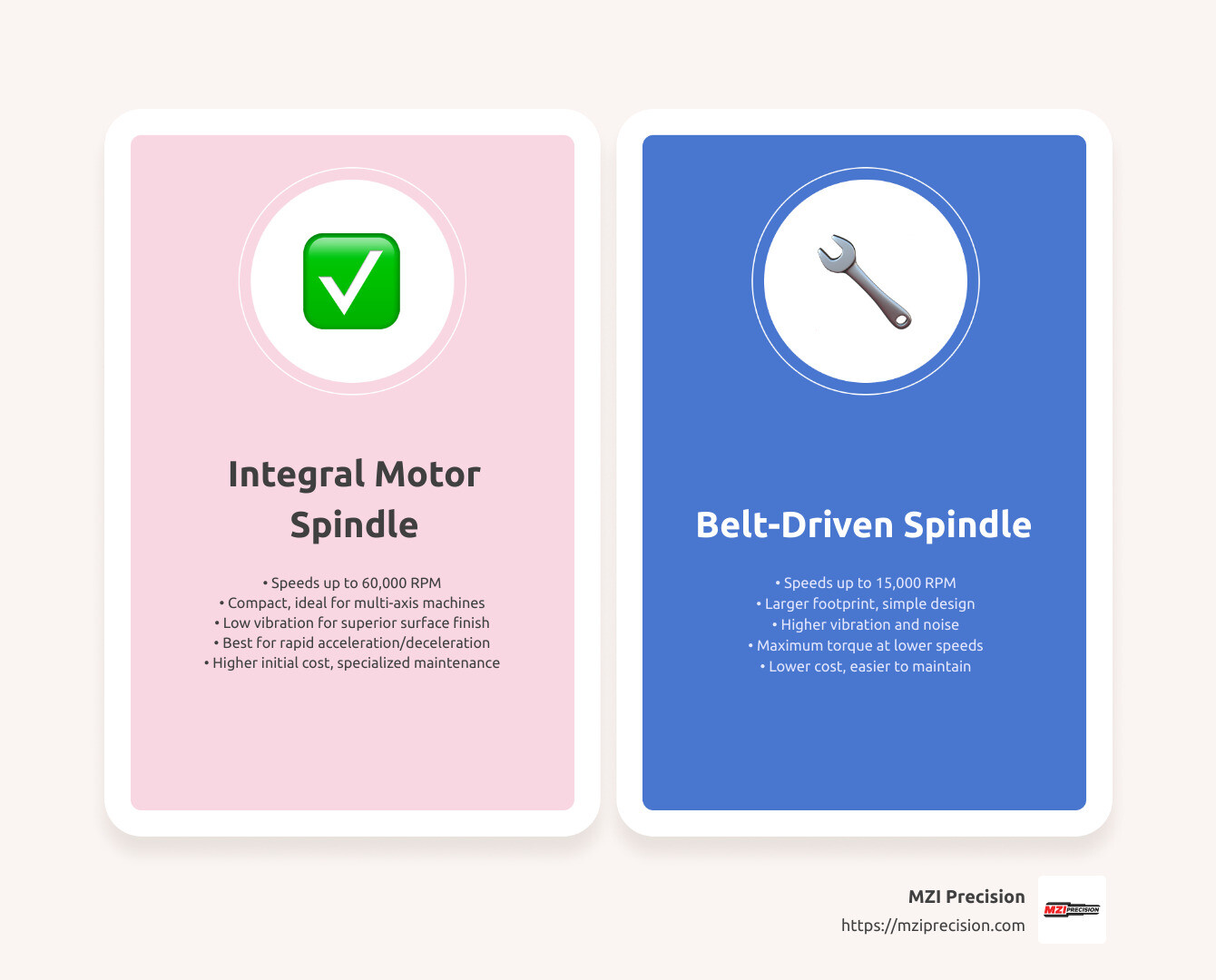
Integral motor spindles (also called motorized spindles) shine when you need speed. If your application demands anything above 15,000 RPM, these designs become increasingly attractive since they can reach an impressive 60,000 RPM in specialized configurations. The aerospace and medical device industries particularly benefit from these high-speed capabilities.
Space-constrained multi-axis machines also benefit tremendously from the compact design of integral motor spindles. When every inch matters in your machine envelope, eliminating bulky belt systems makes a world of difference.
For shops focused on superior surface finishes, integral motor spindles offer another advantage: reduced vibration. By eliminating belt drives, you remove a significant vibration source, resulting in better surface quality and tighter dimensional accuracy. I’ve seen parts go from requiring secondary finishing to coming off the machine ready for assembly after switching to an integral motor spindle.
The direct coupling of motor to shaft also provides snappier acceleration and deceleration—a real advantage for operations with frequent speed changes or complex toolpaths.
Belt-driven spindles still have their place, though! They’re the workhorses of many shops because of their cost-effectiveness and straightforward maintenance. When your budget is tight, you need maximum torque at lower speeds, or your operating environment is particularly harsh, a quality belt-driven spindle can be the perfect solution.
At MZI Precision, we help customers evaluate these trade-offs based on their specific applications and budget constraints. Sometimes the answer isn’t immediately obvious, but understanding your production requirements makes the decision much clearer.
Conclusion
The world of machine tool spindle design is truly where art meets science. Throughout this journey, we’ve seen how spindles serve as the beating heart of precision manufacturing equipment, directly influencing everything from surface finish to dimensional accuracy.
Creating the perfect spindle isn’t about maximizing every specification—it’s about finding the right balance for your specific needs. Like choosing the perfect car, you’re always balancing competing factors: Do you need the raw torque of a heavy-duty pickup or the nimble precision of a sports car?
Machine tool spindle design requires similar thoughtful trade-offs:
– Higher speeds often mean sacrificing some torque
– Increased stiffness may create thermal management challenges
– Greater precision typically comes with higher costs
– Improved durability might add weight and complexity
At MZI Precision, we’ve spent decades perfecting the art of spindle rebuilding. Our hands-on experience spans everything from aerospace components where tolerances are measured in microns to heavy industrial applications where reliability under load is paramount. We’ve seen how the right spindle solution can transform manufacturing operations.
When a customer comes to us with a failing spindle, we don’t just replace worn parts—we partner with them to understand their unique challenges. Sometimes, we can improve the original design to better suit their specific application, extending service life or improving performance beyond the original specifications.
A well-designed and properly maintained spindle delivers remarkable value. Our customers regularly report tangible benefits: parts that meet spec the first time, cutting tools that last significantly longer, reduced machine downtime, and ultimately, lower cost per part. These improvements go straight to the bottom line.
Whether you’re in the market for a complete spindle rebuild or simply seeking advice on optimizing your current equipment, the principles we’ve discussed provide a solid foundation for making informed decisions. Proper maintenance isn’t an expense—it’s an investment in productivity and quality.
For more information about our spindle rebuilding services or to discuss how we might help with your specific manufacturing challenges, contact MZI Precision today. Our team brings both technical expertise and practical shop floor experience to every project, ensuring you get solutions that work in the real world, not just on paper.