


Why Understanding Servo Control is Essential for Precision Motion
Controlling a servo requires sending precise PWM signals to position the motor shaft at exact angles. Here’s what you need to know:
Basic Servo Control Requirements:
– Power: 4.8V-6V DC supply (red wire)
– Ground: Common ground connection (black/brown wire)
– Signal: 50 Hz PWM pulses on control wire (yellow/orange wire)
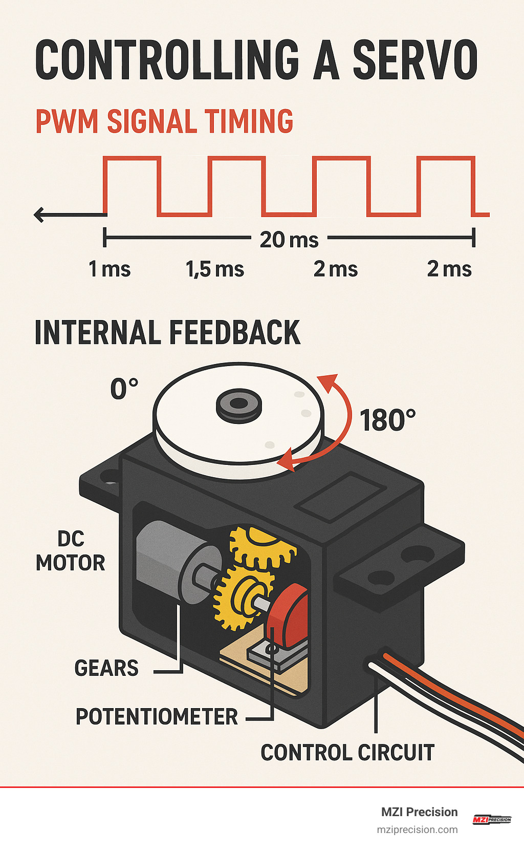
– Pulse Width: 1ms = 0°, 1.5ms = 90°, 2ms = 180°
Servo motors are closed-loop actuators that use internal feedback to maintain precise positions. Unlike regular DC motors, they contain a DC motor, reduction gears, potentiometer, and control circuit all in one package.
Whether you’re building robotic arms, automated positioning systems, or precision manufacturing equipment, servo control forms the backbone of accurate motion systems. The beauty lies in their simplicity – send the right pulse width, and the servo moves to that exact angle and holds it there.
For manufacturing professionals, understanding servo fundamentals helps bridge the gap between basic hobby applications and industrial-grade motion control systems used in CNC machines and automated production lines.
Servo Motor Fundamentals & Types
Think of servo motors as the smart cousins of regular DC motors. While a basic DC motor just spins when you give it power, servo motors are packed with intelligence that makes controlling a servo both precise and reliable.
Inside every servo, you’ll find four key components working together like a well-orchestrated team. The DC motor provides the raw power, but it’s the reduction gears that make the magic happen – they slow down the motor’s high-speed spinning and multiply the torque. This means you get smooth, powerful movement instead of a weak, buzzy mess.
The real genius lies in the potentiometer – a position sensor that constantly tells the servo exactly where its shaft is pointing. This feeds into the control board, which acts like a tiny brain comparing where the servo should be (based on your PWM signal) with where it actually is. When these don’t match, the control board kicks the motor into action until everything lines up perfectly.
This closed-loop system is what separates servos from ordinary motors. Try to push a servo off its commanded position, and it’ll fight back, automatically applying just enough force to stay put. It’s like having a stubborn assistant that refuses to budge from where you told it to go.
Servo specifications matter more than you might think. Most hobby servos run happily on 4.8V to 6V, but voltage affects both torque and speed. A popular SG90 micro servo delivers 1.2 kg·cm of torque at 4.8V but jumps to 1.6 kg·cm at 6V. Larger servos like the MG996R pack serious punch – up to 13 kg·cm at 6V.
Here’s where things get interesting: stall current can be a real surprise. That innocent-looking SG90 normally sips just 100mA, but block its movement and it’ll suddenly demand 650mA. The bigger MG996R is even hungrier, potentially drawing 2.5A when stalled. This is why external power supplies become essential for reliable operation.
How a Servo Works Internally
The internal workings of a servo reveal some clever engineering tricks. The DC motor connects to a series of reduction gears – typically providing gear ratios between 50:1 and 300:1. This gear train is what transforms the motor’s high-speed, low-torque output into the slow, powerful movement that makes servos so useful.
The feedback loop is beautifully simple. A potentiometer mechanically links to the output shaft, creating a voltage that changes as the shaft rotates. The control board continuously compares this feedback voltage with the desired position encoded in your PWM signal’s pulse width.
When these signals don’t match, the control board drives the motor in the right direction until they align. It’s like a persistent perfectionist that won’t rest until everything is exactly where it should be. This system automatically compensates for external forces and maintains position without you having to send constant commands.
Comparing Standard vs Continuous Rotation Servos
Standard servos and continuous rotation servos are built for completely different jobs, and understanding the difference will save you headaches down the road.
Standard servos excel at precise positioning within their roughly 180° travel range. They’re the go-to choice when you need something to move to a specific angle and stay there – perfect for robotic joints, automated positioning systems, or any application where exact angles matter. The movement arc is limited, but the precision is excellent.
Continuous rotation servos take a different approach entirely. They sacrifice the position feedback for unlimited rotation capability. Instead of controlling a servo’s position, your PWM signal now controls speed and direction. A 1.5ms pulse typically stops the motor, shorter pulses spin it clockwise, and longer pulses drive counterclockwise rotation.
The trade-offs are significant. Standard servos provide holding torque – they’ll actively resist being moved from their commanded position. Continuous rotation servos can’t do this since they don’t know where they are. Standard servos respond to PWM with 1ms commanding 0° and 2ms commanding 180°. Continuous servos interpret 1ms as full counterclockwise speed and 2ms as full clockwise speed.
Choose standard servos for precision motion control applications where exact positioning matters. Pick continuous rotation servos when you need unlimited rotation for wheels, conveyor systems, or any application requiring continuous movement rather than precise positioning.
Controlling a Servo: Wiring, Signals & Code
Controlling a servo might seem intimidating at first, but it’s actually quite straightforward once you understand the basics. Think of it like learning to speak a very simple language – servos only understand one type of conversation, and that’s PWM (Pulse Width Modulation) signals.
Every servo uses the same three-wire setup that’s been standard for decades. The red wire carries power (usually 5V), the black or brown wire connects to ground, and the colorful wire – yellow, white, or orange – carries your control signal. This simple interface is what makes servos so popular in everything from hobby projects to industrial manufacturing spindle positioning systems.
The magic happens in the timing. Your servo expects to receive a pulse every 20 milliseconds – that’s 50 times per second. The width of each pulse tells the servo exactly where to move. A 1ms pulse says “go to 0 degrees,” a 1.5ms pulse means “center yourself at 90 degrees,” and a 2ms pulse commands “move to 180 degrees.” It’s that simple.
Here’s where many people run into trouble: power management. Your Arduino’s built-in power supply can provide 500mA through USB or up to 1A through the barrel connector. But servos are hungry little devices, especially when they’re working hard. A small servo might draw 100mA during normal operation, but when it hits an obstacle or stalls, that current can spike to 650mA or more.
That’s why experienced builders always add a 100µF electrolytic capacitor between power and ground. This little component acts like a tiny battery, smoothing out those current spikes that can cause your Arduino to reset unexpectedly. Just remember to watch the polarity – the negative stripe goes to ground.
Don’t forget about grounding either. Your servo’s ground wire must connect to your microcontroller’s ground to create a proper voltage reference. Without this common ground, your control signals become unreliable, and your servo might twitch, jitter, or ignore commands entirely.
For deeper technical details about servo control interfaces, check out this comprehensive analysis that breaks down the timing specifications.
Step-by-Step Guide to Controlling a Servo with Arduino
Let’s walk through setting up your first servo control system. We’ll use Arduino’s built-in Servo library, which handles all the complex timing calculations for you.
Start with the hardware connections. Connect your servo’s red power wire to Arduino’s 5V pin (or an external 5V supply for better performance). The black or brown ground wire goes to Arduino’s GND pin. Finally, connect the signal wire to digital pin 9 – this is arbitrary, but pin 9 works well for our example.
Add that crucial capacitor between 5V and ground. The 100µF electrolytic capacitor should have its negative stripe connected to ground and its positive terminal to 5V. This small addition prevents most power-related headaches.
Now for the fun part – the code:
“`cpp
include
Servo myServo;
void setup() {
myServo.attach(9); // Attach servo to pin 9
}
void loop() {
// Sweep from 0 to 180 degrees
for (int pos = 0; pos <= 180; pos += 1) {
myServo.write(pos);
delay(15);
}
// Sweep back from 180 to 0 degrees
for (int pos = 180; pos >= 0; pos -= 1) {
myServo.write(pos);
delay(15);
}
}
“`
This simple program creates a continuous sweeping motion. The attach() function tells the library which pin controls your servo. The write() function accepts angles from 0 to 180 degrees and automatically converts them to the proper pulse widths.
The Arduino Servo library is surprisingly capable. Most Arduino boards can control up to 12 servos simultaneously, while the Arduino Mega handles up to 48 servos. Each servo gets its own object and can attach to any digital pin.
The 15-millisecond delay between position changes creates smooth motion. Shorter delays make faster movements, while longer delays create slower, more deliberate motion. Experiment with different values to find what works best for your application.
Fine-Tuning & Advanced Controlling a Servo Commands
Once you’ve mastered basic servo control, you’ll want more precision and flexibility. The writeMicroseconds() function gives you direct control over pulse width, opening up possibilities beyond the standard 0-180 degree range.
cpp

// Fine control using microseconds

myServo.writeMicroseconds(1000);  // Minimum position

delay(1000);

myServo.writeMicroseconds(1500);  // Center position

delay(1000);

myServo.writeMicroseconds(2000);  // Maximum position
This approach becomes essential when working with servos that have extended ranges. Some servos respond to pulses as narrow as 500µs or as wide as 2500µs, giving you more than 180 degrees of rotation.
Calibration is where the real magic happens. The attach() function accepts optional minimum and maximum pulse width parameters:
cpp

myServo.attach(9, 544, 2400);  // Pin 9, min 544µs, max 2400µs
This feature lets you squeeze every degree of movement from your servo while preventing it from trying to move beyond its physical limits. Different manufacturers use different pulse ranges, so calibration ensures consistent performance across your servo collection.
Smooth motion programming extends servo life and reduces current spikes. Instead of jumping directly to target positions, gradual transitions create more professional-looking movements:
cpp

void smoothMove(int currentPos, int targetPos, int stepDelay) {

  if (currentPos < targetPos) {

    for (int pos = currentPos; pos <= targetPos; pos++) {

      myServo.write(pos);

      delay(stepDelay);

    }

  } else {

    for (int pos = currentPos; pos >= targetPos; pos--) {

      myServo.write(pos);

      delay(stepDelay);

    }

  }

}
This smooth motion approach reduces mechanical stress and creates more predictable current consumption. Your servos will thank you with longer life and more reliable operation, whether you’re building precision positioning systems or exploring the fundamentals that scale up to industrial motion control applications.
Power Management & Multi-Servo Strategies
When you’re controlling a servo or multiple servos at once, power management becomes your best friend—or your biggest headache if you ignore it. Think of it like feeding a hungry family: one person might be satisfied with a sandwich, but try to feed five teenagers with the same sandwich and you’ll have problems.
Single servos can sometimes get by using your Arduino’s 5 V supply, but it’s walking a tightrope. The moment your servo encounters resistance or needs to hold a heavy load, current spikes can crash your entire system faster than you can say “brownout reset.”
External power supplies are the professional approach. You’ll want something that matches your servo’s voltage sweet spot (usually between 4.8 V and 6 V) while delivering enough current to handle the worst-case scenario. Here’s where the math gets interesting: if you have five SG90 servos, each capable of drawing 650 mA when stalled, you’re looking at potentially 3.25 A total. Smart engineers add a safety margin and spec a 4 A supply.
Those current spikes during servo startup aren’t just numbers on a datasheet—they’re voltage-dropping, microcontroller-resetting reality. A good 100 µF electrolytic capacitor between power and ground acts like a tiny reservoir, smoothing out these spikes before they cause trouble.
Wire gauge matters more than most people realize. Thin wires create voltage drops that can make your servos sluggish or erratic. For runs carrying several hundred milliamps, stick with at least 22 AWG wire for short distances. Go heavier for longer runs—your servos will thank you with consistent performance.
The real game-changer for multi-servo projects is the PCA9685 PWM driver board. This clever little board handles 16 servos using just two Arduino pins through I²C communication. It’s like having a servo orchestra conductor that frees up your Arduino to handle other tasks.
For deeper technical details about servo frequency requirements and timing specifications, this comprehensive resource covers the engineering fundamentals that matter in precision applications.
Safely Powering One or Many Servos
Safe servo power isn’t just about avoiding magic smoke—it’s about building systems that work reliably day after day. Single servo applications can often piggyback on Arduino power if you stay within current limits, but external supplies give you better voltage regulation and peace of mind.
Battery selection depends on your specific needs. NiMH AA cells provide steady voltage but limited runtime. Lithium polymer batteries pack serious capacity and discharge capability, though they demand respect in charging and handling. For stationary setups needing long runtime, lead-acid batteries deliver reliable power without the complexity.
Wall adapters come in two main flavors: switching and linear. Switching adapters are efficient but can introduce electrical noise that sensitive servos might not appreciate. Linear adapters provide cleaner power but generate more heat. Always verify your adapter’s current rating exceeds your total servo requirements—preferably by a comfortable margin.
Here’s a non-negotiable rule: all grounds must connect together. Every servo ground, your power supply ground, and your microcontroller ground need a common connection point. This establishes the voltage reference that makes control signals meaningful and prevents the mysterious behavior that comes from ground loops.
Scaling Up: Controlling a Servo Farm with PCA9685
The PCA9685 opens up possibilities that seemed impossible with basic Arduino pins. You can control up to 992 servos using I²C addressing and daisy-chaining techniques. Each board manages 16 servos and accepts one of 62 possible I²C addresses from 0x40 to 0x7F.
Setting up your first PCA9685 is surprisingly straightforward:
“`cpp
include
include
Adafruit_PWMServoDriver pwm = Adafruit_PWMServoDriver();
void setup() {
pwm.begin();
pwm.setPWMFreq(50); // 50 Hz for servos
}
void loop() {
// Control servo on channel 0
pwm.setPWM(0, 0, 150); // ~1 ms pulse (0°)
delay(1000);
pwm.setPWM(0, 0, 300); // ~1.5 ms pulse (90°)
delay(1000);
pwm.setPWM(0, 0, 450); // ~2 ms pulse (180°)
delay(1000);
}
“`
The PCA9685’s 12-bit resolution gives you 4096 steps across each 20 ms period. At 50 Hz, each step represents about 4.88 µs. Converting pulse widths becomes a simple calculation: 1000 µs ÷ 4.88 µs gives you approximately 205 steps for 0°, while 2000 µs ÷ 4.88 µs equals roughly 410 steps for 180°.
Address selection uses solder jumpers on the board itself. The default address (0x40) requires no jumpers at all. By adding jumpers to the A0, A1, A2, A3, A4, and A5 pads, you create binary address offsets that enable 64 unique addresses per I²C bus. It’s like giving each board its own unique postal address in your servo neighborhood.
This scalability makes the PCA9685 approach particularly valuable in precision manufacturing applications where multiple servos need coordinated control—similar to how industrial manufacturing spindles require precise coordination in automated production systems.
Troubleshooting, Calibration & Safety FAQs
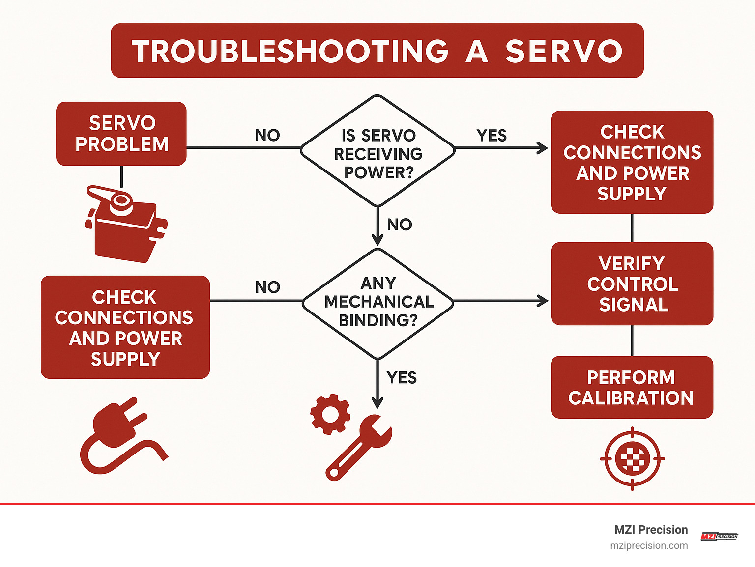
Troubleshooting servo control issues requires systematic diagnosis of power, signal, and mechanical systems. Common problems include jitter, limited range, microcontroller resets, and mechanical binding. Understanding root causes enables quick resolution and prevents recurring issues.
Power-related problems manifest as erratic behavior, reduced torque, or system resets. Insufficient current capacity, voltage drops, and electrical noise are primary culprits. Mechanical issues include binding, gear wear, and potentiometer failure. Signal problems involve timing errors, noise interference, and grounding issues.
Diagnostic tools help isolate problems. A multimeter measures voltages and currents, revealing power distribution issues. An oscilloscope displays signal timing and quality, showing pulse width accuracy and electrical noise. Mechanical inspection identifies binding, wear, or damage.
Why Does My Servo Jitter When Controlling a Servo?
Servo jitter typically results from power supply instability, electrical noise, or inadequate grounding. When supply voltage fluctuates, the servo’s control circuit struggles to maintain consistent position commands, resulting in visible oscillation around the target position.
Electrical noise from switching power supplies, motor controllers, or digital circuits can interfere with servo control signals. The servo interprets this noise as position commands, causing unwanted movement. Proper grounding and signal shielding minimize noise interference.
Insufficient current capacity causes voltage drops during servo movement. As the servo draws current, supply voltage decreases, reducing available torque and causing position instability. The servo may oscillate as it attempts to reach positions requiring more torque than available at the reduced voltage.
Solutions for servo jitter:
– Add 100-470µF electrolytic capacitor near servo power connections
– Use separate power supply for servos, not Arduino 5V rail
– Implement proper star grounding with single ground connection point
– Shield control signal wires in noisy environments
– Check for loose connections in power and ground circuits
How Do I Calibrate End-Stops When Controlling a Servo?
Servo calibration ensures full range utilization and prevents mechanical binding. Different servo manufacturers use varying pulse width ranges, and mechanical assemblies may require limited travel to prevent collision.
The attach() function’s optional parameters enable range adjustment:
cpp

myServo.attach(9, 1000, 2000);  // Standard 1-2ms range

myServo.attach(9, 500, 2500);   // Extended 0.5-2.5ms range

myServo.attach(9, 1200, 1800);  // Limited range for mechanical constraints
Iterative calibration involves testing minimum and maximum positions while monitoring for mechanical binding or excessive current draw. Start with conservative ranges and gradually extend until reaching desired travel or mechanical limits.
An oscilloscope provides precise pulse width measurement for calibration verification. Connect the probe to the servo signal wire and verify that write(0) produces the expected minimum pulse width and write(180) produces the expected maximum pulse width.
Some servos accept pulse widths outside the standard 1-2ms range, enabling greater than 180° rotation. Testing with writeMicroseconds() reveals actual servo capabilities:
cpp

// Test extended range carefully

myServo.writeMicroseconds(500);   // Test minimum

delay(1000);

myServo.writeMicroseconds(2500);  // Test maximum
What Is the Best Way to Control a Servo on Raspberry Pi?
Raspberry Pi servo control faces unique challenges due to the operating system’s non-real-time nature. Unlike Arduino’s dedicated microcontroller, Raspberry Pi runs Linux, which can interrupt PWM generation for system tasks, causing servo jitter.
Hardware PWM solutions provide stable servo control on Raspberry Pi. The Pi Servo HAT uses a dedicated PCA9685 chip to generate consistent PWM signals independent of the main processor. This approach eliminates timing jitter and frees the Pi’s CPU for other tasks.
Python servo control with Pi Servo HAT:
“`python
import time
from adafruit_servokit import ServoKit
kit = ServoKit(channels=16)
Control servo on channel 0
kit.servo[0].angle = 0 # 0 degrees
time.sleep(1)
kit.servo[0].angle = 90 # 90 degrees
time.sleep(1)
kit.servo[0].angle = 180 # 180 degrees
“`
Software PWM using GPIO libraries works for single servos or non-critical applications but suffers from timing instability. The pigpio library provides better timing than RPi.GPIO but still can’t match hardware PWM consistency.
Enable I²C on Raspberry Pi before using servo HATs:
“`bash
sudo raspi-config
Steer to Interfacing Options > I2C > Enable
sudo reboot
“`
The Raspberry Pi Servo HAT supports up to 16 servos and includes power distribution for external servo power supplies. This combination provides industrial-grade servo control suitable for precision applications.
Conclusion
Mastering controlling a servo opens up a world of precision motion possibilities that extends far beyond weekend tinkering. Whether you’re building your first robotic arm or designing complex automated systems, understanding servo fundamentals gives you the confidence to tackle increasingly sophisticated projects.
The beauty of servo control lies in its scalability. Today’s simple single-servo project becomes tomorrow’s multi-axis robotic system. Start small with basic Arduino control to grasp PWM timing and power requirements. Then expand to multi-servo systems using PCA9685 drivers when your projects demand more complexity.
Each challenge you solve builds valuable knowledge. That servo jitter you troubleshoot teaches you about power supply design. The calibration process you master for hobby servos introduces concepts used in industrial motion control systems. These fundamentals create a solid foundation for understanding more advanced motion control applications.
At MZI Precision, we see the natural progression from learning basic servo principles to working with industrial manufacturing spindles. The same concepts that govern controlling a servo – feedback systems, precise timing, and power management – apply to the high-precision spindle systems we rebuild for aerospace, defense, automotive, and solar energy manufacturing.
While hobby servos teach you the basics, industrial manufacturing spindle repair and rebuilding requires the expertise that comes from years of hands-on experience. Our team understands that manufacturing precision demands reliability you can count on, whether you’re producing critical aerospace components or solar energy systems.
The journey from understanding basic servo control to implementing industrial-grade motion solutions might seem like a big leap, but every expert started exactly where you are now. Master these servo fundamentals, and you’ll have the knowledge to tackle whatever motion control challenges come your way.
For more information about our 3 axis servo motor controller, AC servo motor for CNC machine, and CNC motors services, contact our team. We’re here to help bridge the gap between learning servo fundamentals and implementing the precision motion control solutions that keep manufacturing operations running smoothly.
Every motion control expert started with the basics. Take your time, experiment safely, and enjoy the process of learning how these remarkable devices work. Your future self will thank you for building this solid foundation.