


Servo Motor Control System: 10 Powerful Tips for Success 2025
Why Servo Motor Control Systems Drive Modern Manufacturing Precision
A servo motor control system is a closed-loop motion control technology that uses feedback sensors to precisely control position, speed, and torque in industrial applications. These systems combine a servo motor, drive amplifier, controller, and feedback device to achieve positioning accuracy as fine as 0.01 degrees in high-end manufacturing.
Key components of a servo motor control system:
– Servo motor – Converts electrical signals into precise mechanical motion
– Drive/amplifier – Powers and controls the motor based on command signals
– Controller – Processes commands and manages the control loop
– Feedback sensor – Monitors actual position/speed and reports back to controller
– Closed-loop control – Continuously compares desired vs actual position to minimize error
Common control methods:
– PWM (Pulse Width Modulation) at 50 Hz frequency
– PID control algorithms for stability and accuracy
– Position, velocity, and torque control modes
Servo systems act as “mechanical slaves” that precisely follow commands – a concept dating back to James Watt’s steam engine governor in the 1700s. Today’s digital servo systems achieve the precision that makes modern CNC machining, robotics, and automated manufacturing possible.
For manufacturing companies working with high-precision spindles and motion control, understanding servo systems is critical. These systems directly impact product quality, cycle times, and equipment reliability in aerospace, medical device manufacturing, and precision machining operations.
Must-know servo motor control system terms:
– 3 axis servo motor controller
– servo motor feedback repair
– servo motor preventive maintenance
Why This Guide Matters
Understanding servo motor control systems is essential for precision manufacturing. Whether you’re designing automated production lines, maintaining CNC equipment, or troubleshooting spindle performance issues, servo systems are the backbone of modern industrial motion control.
At MZI Precision, we’ve seen how proper servo system knowledge directly translates to improved manufacturing reliability and reduced downtime. When engineers understand these systems, they make better decisions about equipment selection, maintenance schedules, and troubleshooting approaches.
What Is a Servo Motor Control System?
A servo motor control system is a feedback-controlled mechanism that moves loads with incredible precision using closed-loop control. The word “servo” comes from the Latin “servus,” meaning slave – these systems obediently follow commands with accuracy that would make a Swiss watchmaker jealous.
The story of servo control dates back to the late 1700s, when James Watt created his centrifugal governor for steam engines. This mechanical device automatically kept engine speed steady by sensing rotation speed and adjusting steam flow accordingly. Modern servo motor control systems work on the same principle – just with electronic precision Watt couldn’t have imagined.
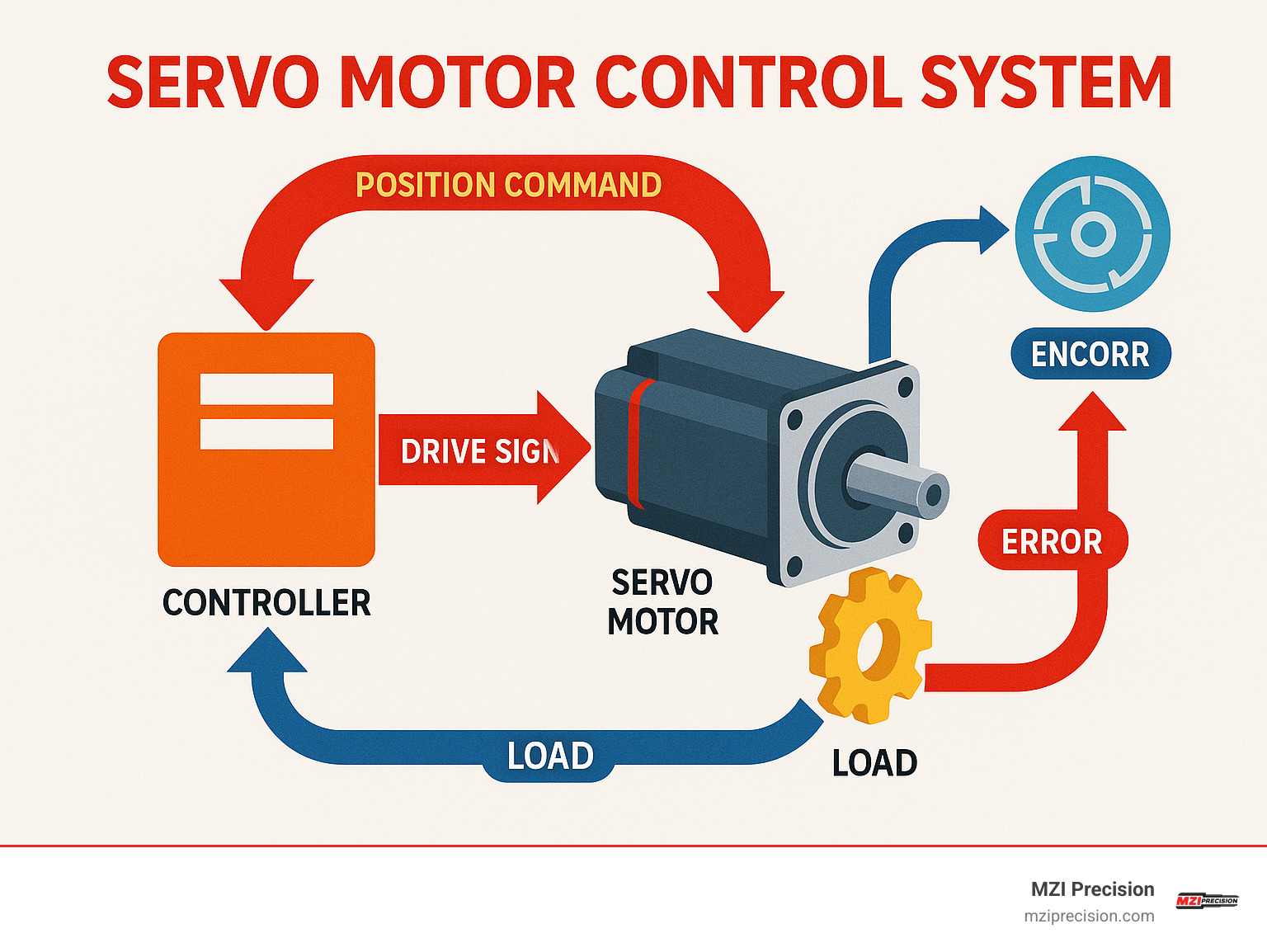
Servo systems use negative feedback control. The system constantly compares actual position (measured by a feedback sensor) with the desired position. Any difference creates an error signal that tells the controller exactly how to correct the position. This closed-loop approach achieves positioning accuracy of 2×10⁻⁵ degrees in high-end systems.
Unlike stepper motors that follow commands blindly, servo systems continuously monitor their performance and make corrections. This makes them perfect for precision manufacturing applications requiring speed, accuracy, and the ability to handle changing loads – exactly what we see with industrial manufacturing spindles.
Key Performance Metrics
Torque delivery is where servo motors excel. They deliver high torque even at low speeds and maintain consistent torque across their operating range. Industrial servo systems handle sudden load spikes up to three times their rated power – crucial for varying cutting loads on manufacturing spindles.
Speed control precision directly impacts finished product quality. AC servo motors get speed from input frequency, while DC systems offer straightforward current control. This level of speed control makes the difference between perfect parts and expensive scrap in precision machining.
Resolution and accuracy depend on encoder choice. Standard setups use 2,500 PPR incremental encoders, while high-end applications use 20-bit absolute encoders. Advanced systems provide over 4 million counts per revolution through interpolation techniques.
Bandwidth measures system response speed. Higher bandwidth means servos follow rapid position changes more accurately, crucial for high-speed manufacturing where every millisecond counts.
Steady-state error measures how close you get to perfect positioning. Quality servo systems minimize the difference between commanded and actual position. PID control algorithms work to reduce this error and improve dynamic response.
Core Components & Feedback Fundamentals
A servo motor control system is like a well-orchestrated team where each member has a specific job, working together to achieve precision motion impossible for any single component alone.

The servo motor converts electrical energy into precise mechanical motion. In industrial manufacturing spindle applications, we typically see brushless DC and AC servo motors because they handle demanding conditions. Brushless motors are popular because they eliminate brush wear, meaning less maintenance and more reliable operation for critical spindle systems.
The drive or amplifier takes gentle command signals and converts them into powerful electrical signals the motor needs. It manages voltage and current waveforms while monitoring safety with features like overcurrent protection. When spindles handle varying loads, the drive ensures everything stays smooth and controlled.
The controller processes motion commands and manages the entire control loop, making split-second decisions about system response. Modern controllers coordinate multiple axes simultaneously, essential for complex manufacturing spindle operations where precision timing matters.
The feedback sensor constantly monitors actual performance and reports back to the controller. This component is critical – without accurate feedback, even the best motor and drive can’t deliver the precision modern manufacturing demands.
The power supply provides the foundation. Servo motors can be power-hungry, especially during acceleration or when handling heavy loads. Properly sized power supplies ensure spindle systems have energy when needed.
The Role of Feedback in a Servo Motor Control System
Feedback transforms an ordinary motor into a precision servo motor control system. Without feedback, you’d be driving with your eyes closed – you might get lucky, but can’t count on arriving exactly where intended.
The feedback loop works like a conversation between controller and motor. The controller commands “go to this position,” the motor moves, the encoder reports “here’s where I actually am,” and the controller responds with corrections if needed. This happens hundreds or thousands of times per second.
Most industrial systems use cascade control – loops within loops. The position loop handles the big picture, ensuring you reach the target. The velocity loop manages movement speed, converting position errors into speed commands. The current loop is the fastest responder, controlling motor torque by managing current flow.
This layered approach gives servo systems remarkable ability to handle changing conditions while maintaining precision. When manufacturing spindles encounter varying loads or disturbances, these multiple loops work together to keep everything on track.
Types of Feedback Devices
Potentiometers are simple and inexpensive, providing absolute position feedback, but they’re only suitable for basic applications. In industrial manufacturing spindle work, you’ll rarely see these because precision isn’t adequate.
Incremental encoders are the workhorses of the servo world. These optical devices use perforated discs and light detection to count pulses as motors turn. A typical 1000-line encoder provides 0.36° resolution per pulse, and with quadrature signals, you get direction information. The trade-off is needing to establish home position at startup.
Absolute encoders are the premium choice when you need to know exact position immediately upon power-up. They’re essential when position must be known instantly – like manufacturing spindles that need to resume exactly where they left off after power interruption. Modern absolute encoders provide up to 20-bit single-turn accuracy.
Resolvers are the tough guys of feedback devices. These electromagnetic devices handle extreme temperatures, vibration, and harsh environments that would destroy other sensors. They’re valuable in demanding industrial applications where decades of reliability matter more than ultimate precision.
| Feedback Type | Resolution | Cost | Environment | Absolute Position |
|---|---|---|---|---|
| Potentiometer | Low | Low | Limited | Yes |
| Incremental Encoder | High | Medium | Good | No |
| Absolute Encoder | Very High | High | Good | Yes |
| Resolver | Medium | High | Excellent | Yes |
For high-precision manufacturing spindles, we typically recommend absolute encoders or high-resolution incremental encoders, depending on whether you need immediate position knowledge on startup.
Control Techniques, PWM & Loop Tuning
The magic of modern servo motor control systems happens in sophisticated algorithms that process feedback and generate precise motor commands. These control techniques act as the “brain” making split-second decisions thousands of times per second to keep industrial spindles exactly where needed.
PID control forms the foundation of most servo systems, combining three essential elements. The Proportional term provides immediate correction when it detects position errors. The Integral term eliminates tiny steady-state errors that accumulate over time. The Derivative term predicts system direction to prevent overshoot and improve stability.
Getting PID tuning right is critical for industrial manufacturing spindles. We’ve seen systems oscillate wildly because gains were too high, and others respond sluggishly because tuning was too conservative. It’s a delicate balance directly impacting machining precision and cycle times.
Feedforward control takes servo performance to the next level by being proactive rather than reactive. Instead of waiting for position errors, feedforward algorithms anticipate system needs based on commanded motion. When CNC programs call for rapid acceleration, feedforward control calculates required torque and applies it immediately, dramatically reducing following errors during high-speed operations.
Modern systems also employ adaptive control techniques that adjust behavior based on changing conditions. As spindle bearings wear or cutting loads vary, adaptive systems modify control parameters automatically. Field-oriented control for AC servo motors optimizes magnetic field orientation for maximum torque efficiency.
PWM (Pulse Width Modulation) is how servo drives control motor power. While hobby servos use simple 50 Hz PWM signals with 1-2 ms pulse widths, industrial servo drives operate at much higher frequencies – typically 10-20 kHz. This higher frequency creates smoother motor operation and reduces audible noise problematic in precision manufacturing.
The duty cycle of PWM signals determines average power reaching the motor. Industrial drives incorporate dead-band compensation to account for switching delays, ensuring accurate performance even at very low speeds where precision positioning is critical.
Open-Loop vs Closed-Loop Strategies
Open-loop systems like stepper motors send commands without verifying results. This works for applications with predictable loads where occasional minor positioning errors won’t cause problems. The advantages are simplicity and lower cost.
Closed-loop servo systems continuously monitor performance and make corrections. This makes servo systems essential for precision manufacturing spindles where even small positioning errors can ruin expensive parts.
Cascade control using multiple nested loops (position, velocity, and current) delivers superior performance required for demanding industrial manufacturing applications. This approach is standard in high-performance spindle systems.
Interfacing Microcontrollers & Networks
For serious industrial applications, EtherCAT networks provide deterministic communication essential for coordinated multi-axis motion. Update rates under 1 millisecond ensure all axes stay perfectly synchronized – critical for complex machining operations.
CANopen networks offer robust communication in harsh industrial environments where electromagnetic interference and temperature extremes are common. This reliability makes them popular in aerospace and defense manufacturing.
PC-based controllers running specialized motion control software coordinate complex multi-axis operations while integrating with broader manufacturing execution systems. These platforms handle sophisticated motion profiles required for advanced manufacturing processes.
Standalone servo drives with built-in motion controllers simplify system architecture while improving reliability. By eliminating separate controller hardware, these integrated solutions reduce potential failure points – valuable for critical spindle applications.
Designing & Selecting the Right Servo Motor Control System
Choosing the right servo motor control system has a logical path through the complexity. We’ve helped countless manufacturers steer this process successfully.

Start with actual application needs rather than impressive technical specs. We’ve seen projects where engineers selected overpowered systems adding unnecessary cost, or underpowered systems that couldn’t meet performance requirements.
Application analysis forms the foundation. Consider what your system actually needs – simple point-to-point moves like pick-and-place, or complex coordinated motion like CNC machining. Duty cycle matters too. Continuous operation needs different thermal management than occasional moves.
Load characteristics often surprise engineers new to servo systems. Calculate total inertia – not just your load, but everything the motor accelerates including couplings and gearing. Keep inertia ratio (load to motor) below 30:1 for good dynamic response.
Power requirements scale dramatically with speed. Doubling move speed requires eight times the power because power scales with 1/T³. This relationship is crucial for sizing motors and power supplies correctly.
Environmental factors can make or break servo installations. Industrial spindle applications involve cutting fluids, metal chips, vibration, and temperature swings. Standard IP53 protection works for clean environments, but harsh conditions may require IP65, IP66K, or IP67 ratings.
Step-by-Step Selection Checklist for Engineers
Define your motion profile first. Document exact movements needed – travel distance, maximum speed, acceleration rates, and positioning accuracy. Be realistic about requirements. Asking for 0.001° accuracy when 0.01° works fine just adds cost and complexity.
Calculate torque requirements for three conditions: peak torque for acceleration, continuous torque for steady-state operation, and holding torque for stationary loads. Include safety factors because real-world conditions are rarely as clean as calculations suggest.
Choose your motor type based on application needs. Brushed DC motors offer simple control and lower cost but need more maintenance. Brushless DC motors provide better efficiency and reliability with more complex control. AC servo motors excel in high-power applications.
Match drive specifications to motor selection. Servo drives must supply adequate voltage and current. Don’t forget regenerative braking for frequent deceleration applications. Slight drive oversizing often pays off in better performance and longer life.
Select your controller or network based on system complexity. Simple applications work with standalone drives, while complex multi-axis systems benefit from centralized motion controllers. Consider future expansion needs.
Verify feedback requirements by working backward from accuracy needs. Higher resolution encoders cost more and may not improve system performance if other factors limit accuracy.
Safety & Compliance Essentials
Electrical safety starts with proper grounding to prevent ground loops and reduce electromagnetic interference. Use shielded cables for signals and maintain separation between power and signal conductors.
Emergency stop integration is mandatory in most industrial applications. Modern servo drives provide safe torque-off (STO) functions that remove motor power while maintaining position feedback for monitoring.
Compliance standards typically include UL certification for North American markets and CE marking for European compliance. IP ratings specify environmental protection – ensure selections match actual operating conditions.
Mechanical safety requires proper guarding, limit switches, and mechanical stops. High-performance servo systems move faster and with more force than people expect.
Applications, Troubleshooting & Maintenance Best Practices
Modern manufacturing facilities showcase servo motor control systems everywhere – these precision workhorses have become the backbone of industrial automation, delivering the accuracy and reliability that modern production demands.
Industrial robotics uses coordinated servo control in multi-axis robotic arms for welding and assembly. Each joint relies on servo positioning to achieve smooth, precise motion paths, with multiple servo systems working together through position feedback.
CNC machining showcases servo systems at their finest. Computer-controlled machine tools depend on servo positioning for sub-millimeter accuracy. The combination of precise speed control and positioning capability makes these systems perfect for complex machining operations in aerospace and medical device manufacturing.
Packaging lines demonstrate servo speed and synchronization capabilities. High-speed packaging equipment uses servo control for conveyor speeds, cutting mechanisms, and product placement. Multiple axis coordination with precise timing enables efficient packaging across industries.
At MZI Precision, we’ve seen how servo motor control systems improve manufacturing spindle performance. When precision spindles integrate with servo control, results include better surface finishes, tighter tolerances, and more consistent part quality – particularly valuable in aerospace manufacturing where specifications leave no room for error.
Common Troubleshooting Steps in a Servo Motor Control System
Most servo problems fall into predictable categories, each with specific troubleshooting approaches.
Stall current issues occur when servo motors draw excessive current but won’t move. Check for mechanical binding first – loose couplings or contaminated bearings can cause this. Verify load calculations were correct and the motor can handle required torque. Review drive parameter settings, as incorrect configuration creates apparent stall conditions.
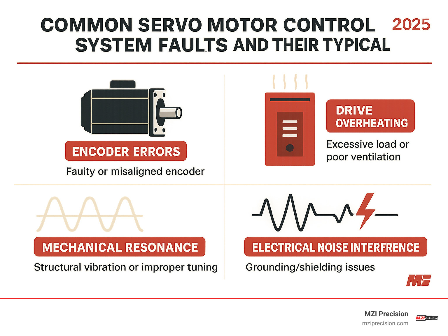
Runaway conditions create dangerous situations when motors take off uncontrolled. Feedback problems are usually the culprit. Check encoder connections for loose wires causing erratic behavior. Verify encoder phasing matches drive settings and feedback device specifications match drive expectations. Sometimes incorrect PID parameters create instability.
Encoder miscounts reveal themselves through position errors accumulating over time. These gradual errors often indicate contamination on encoder discs or intermittent cable connections. Inspect optical encoders for dust or oil contamination, and check cable connections for wear or corrosion.
Loop instability manifests as oscillation or hunting behavior. This typically results from improper tuning. Start with conservative PID settings and gradually increase gains while monitoring system response. Mechanical resonances may require notch filters or system stiffness changes.
Electrical noise problems can be intermittent and challenging. Servo systems are sensitive to electromagnetic interference, so proper installation is crucial. Ensure signal cables are properly shielded with adequate separation from power cables. Verify proper grounding practices.
Best Practices for Longevity
Servo systems are precision instruments requiring appropriate care. Like high-precision spindles, servo systems reward proper maintenance with years of reliable service.
Proper cooling is often overlooked until problems develop. Servo motors and drives generate significant heat, and excessive temperatures dramatically reduce component life. Maintain recommended clearances around drives and ensure adequate ventilation.
Periodic tuning keeps systems performing optimally. System characteristics drift over time due to mechanical wear, temperature changes, and component aging. Establish regular tuning schedules, especially for critical applications.
Preventive maintenance should cover cleaning encoder discs and optical sensors, checking cable connections and strain reliefs, verifying proper lubrication of mechanical components, and testing emergency stop functions. These routine tasks prevent most servo system failures and ensure reliable operation when needed most.
Frequently Asked Questions about Servo Motor Control Systems
Manufacturing engineers consistently ask the same questions about servo motor control systems – the real-world concerns that impact precision manufacturing systems and spindle performance.
What is the difference between an AC and DC servo motor?
DC servo motors are the reliable workhorses of the servo world. They use direct current, making them simpler to understand and control. Brushed DC motors offer inexpensive solutions that are easy to implement, but require regular brush replacement as scheduled maintenance.
Brushless DC motors eliminate brush maintenance while offering higher efficiency and better reliability, but need more sophisticated electronic controls.
AC servo motors are the heavy-duty champions of industrial manufacturing. These brushless motors use alternating current and offer excellent reliability with impressive power density. They’re more complex to control since they require sophisticated drives managing three-phase power, but this complexity pays dividends in performance.
For industrial manufacturing spindle applications, AC servo motors frequently win because of their robustness and high power capability. When machining aerospace components or medical devices, that extra reliability and power density makes the difference between meeting tight tolerances and scrapping expensive parts.
How does PWM translate to precise angle control?
PWM (Pulse Width Modulation) controls servo position by varying control pulse width. In simpler systems, a 1.5 ms pulse centers the servo at 90°, while 1.0 ms and 2.0 ms pulses move it to 0° and 180° respectively. The servo’s internal control circuit compares pulse width to an internal reference and drives the motor until feedback confirms position matches the command.
Industrial servo motor control systems use much higher frequency PWM – typically 10-20 kHz – to control motor current and voltage with incredible precision. The drive’s control algorithm constantly calculates required PWM duty cycle based on position error, velocity, and current feedback, creating smooth, precise motion that makes modern CNC machining possible.
When should I use dual-loop feedback?
Dual-loop feedback is like having two sets of eyes – one watching the motor, another watching what’s happening at the load. This becomes invaluable when there’s mechanical backlash or compliance between motor and actual load.
One encoder monitors motor position (providing excellent velocity and acceleration feedback), while another monitors actual load position (ensuring precise final positioning). This configuration shines in long drive trains with significant backlash, belt or chain drives with inherent elasticity, and gearboxes with backlash.
Dual-loop feedback allows systems to achieve smooth motion using motor feedback while maintaining precise positioning using load feedback. For manufacturing engineers working with high-precision spindles, dual-loop feedback can make the difference between achieving tight tolerances required for aerospace or medical device manufacturing and dealing with costly rework.
Conclusion
Understanding servo motor control systems is essential for precision manufacturing and industrial automation. These sophisticated systems combine mechanical precision with electronic intelligence to achieve the accuracy and reliability that modern manufacturing demands.
At MZI Precision, we’ve witnessed how proper servo system knowledge translates directly into improved manufacturing outcomes. Whether you’re maintaining existing equipment, designing new automated systems, or troubleshooting performance issues, the principles covered in this guide provide the foundation you need for success.
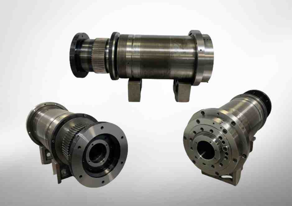
Our expertise in industrial manufacturing spindle repair and rebuilding gives us unique perspective on how servo motor control systems integrate with precision mechanical components. When high-speed industrial manufacturing spindles pair with properly configured servo control systems, the result is manufacturing capability that consistently meets demanding requirements of aerospace, medical device, and precision machining applications.
The magic happens when precision meets power. We’ve seen manufacturing operations transform their productivity when they understand how servo feedback loops improve spindle performance. The closed-loop control becomes especially critical when spindles operate at high speeds with varying loads – exactly where feedback control makes the difference between acceptable and exceptional results.
Successful servo system implementation lies in understanding specific application requirements, selecting components that work together harmoniously, and maintaining systems with appropriate care. With the right knowledge and approach, servo motor control systems provide the precision and reliability that modern manufacturing absolutely requires.
Your servo system is only as good as its weakest link. When that system includes a precision spindle that’s been properly maintained and rebuilt to exact specifications, you’ve created manufacturing capability that can handle whatever challenges your industry presents.
For more information about how servo-integrated spindle systems can improve your manufacturing operations, explore our spindle services and find how precision truly meets power in modern industrial applications.